
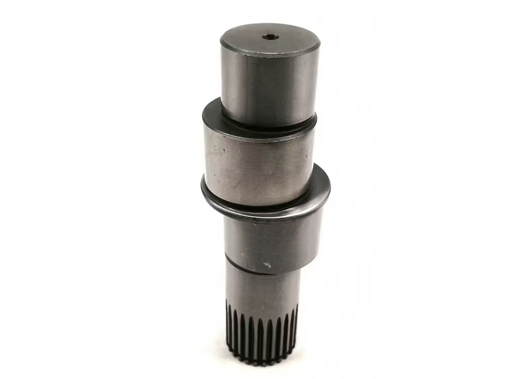
RV Crankshafts
The eccentric journals drive the cycloidal stage in an RV reducer.
- We machine the main journals from the drawing datum.
- Eccentric offset and phase are checked before release.
We machine crankshafts and gear shafts from customer drawings. Input shafts and output shafts can also be made for robot reducer assemblies.
Before production, we review how the journals and drive features relate to the drawing datum. The process plan then follows that relationship through machining and final inspection.
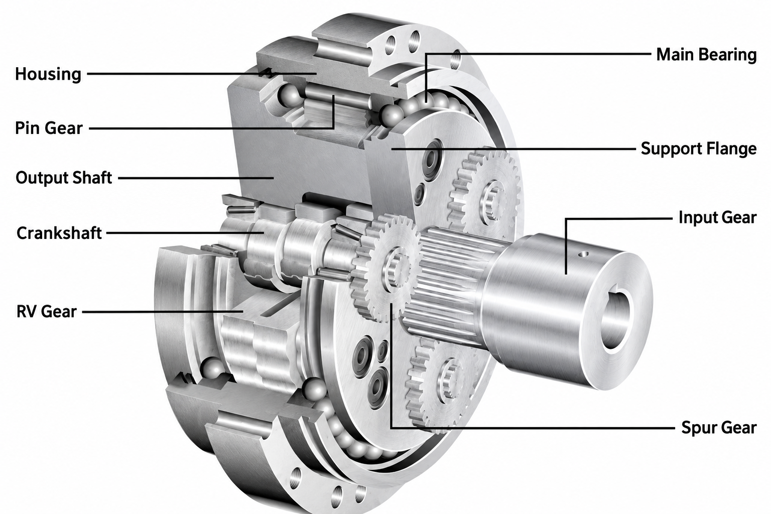
A finished diameter can be within tolerance while the shaft still runs out in the assembly. The same problem occurs when an eccentric journal has the right size but the wrong angular position.
We start with the functional datum on the drawing. That datum is carried through the setup plan and used again when the finished shaft is inspected.
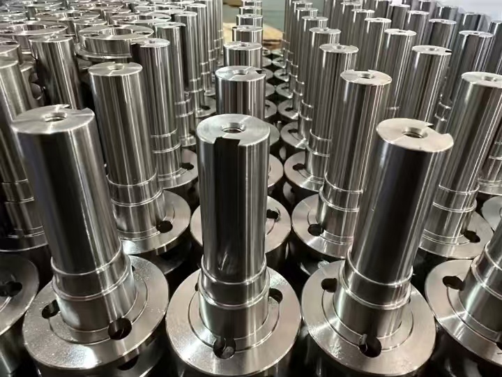
The parts below cover common reducer shaft designs. Send the drawing if your shaft has a different form and we will review it as a custom part.
The eccentric journals drive the cycloidal stage in an RV reducer.
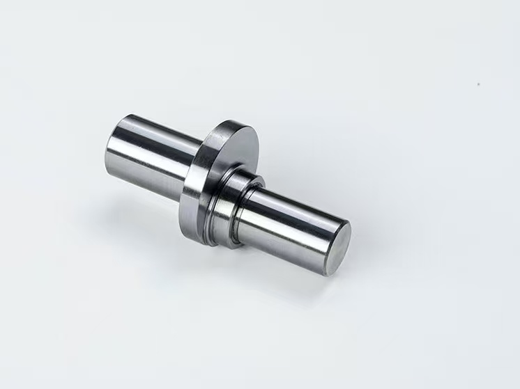
The offset journal produces the motion specified by the reducer design.
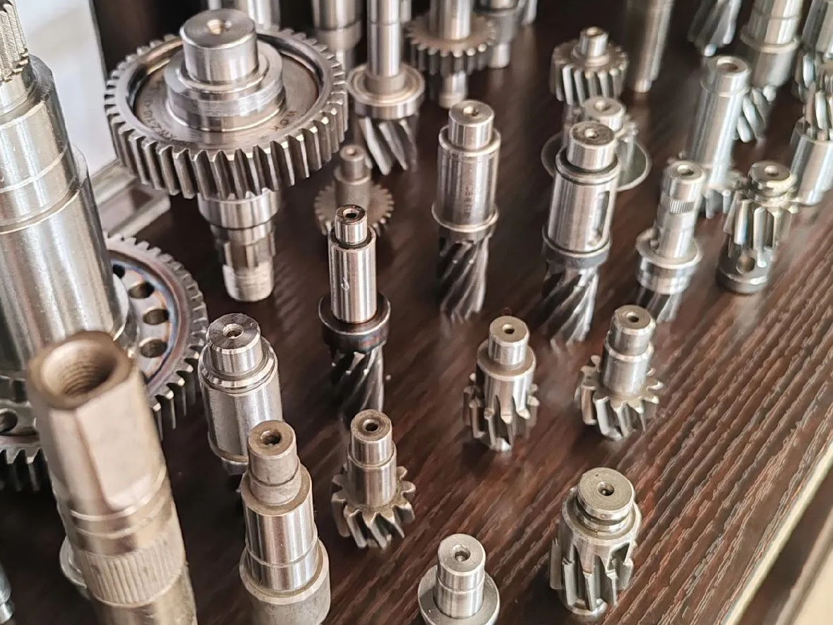
The gear and shaft are made as one part so the tooth datum stays tied to the journals.
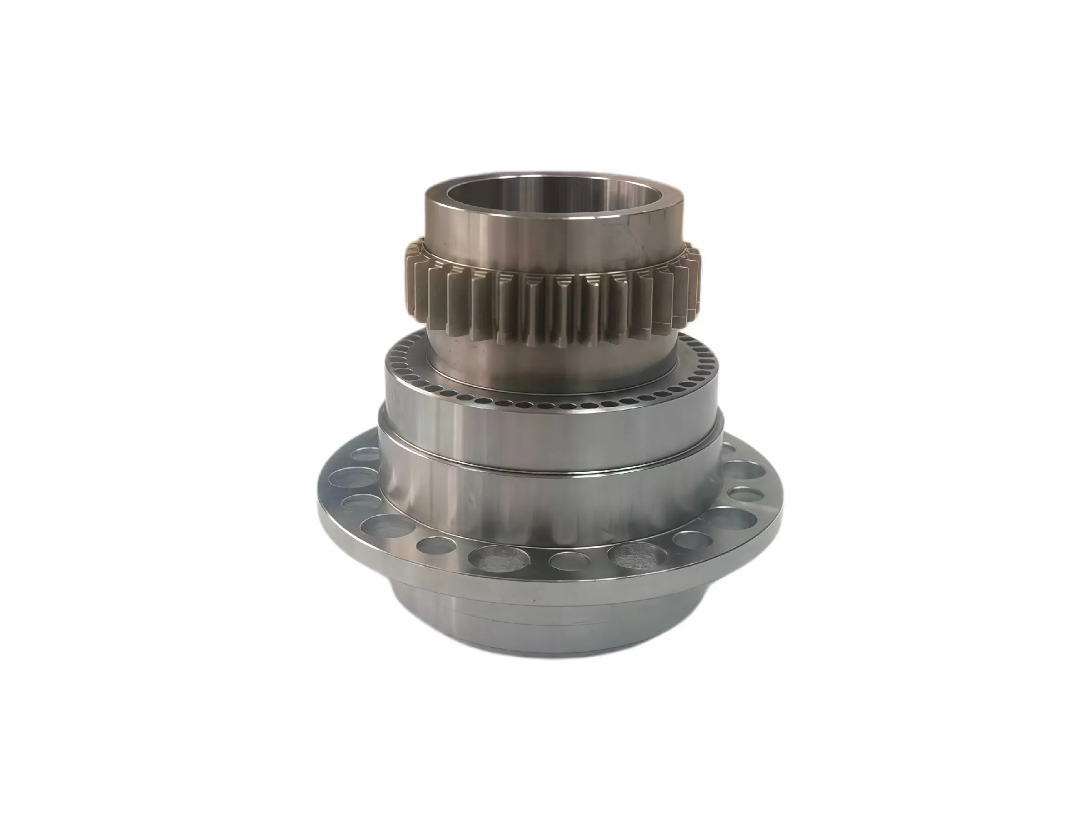
A sun gear shaft combines the planetary gear with its bearing and drive interfaces.
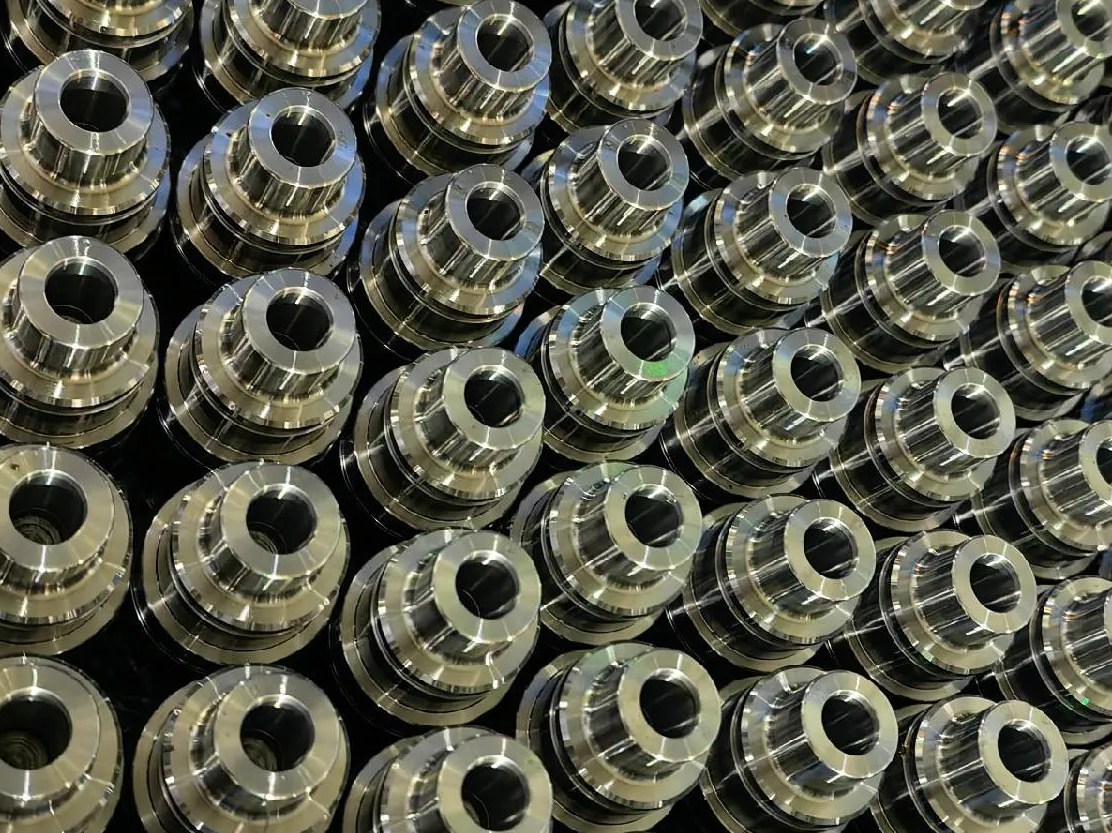
The input shaft carries motion from the motor into the reducer.
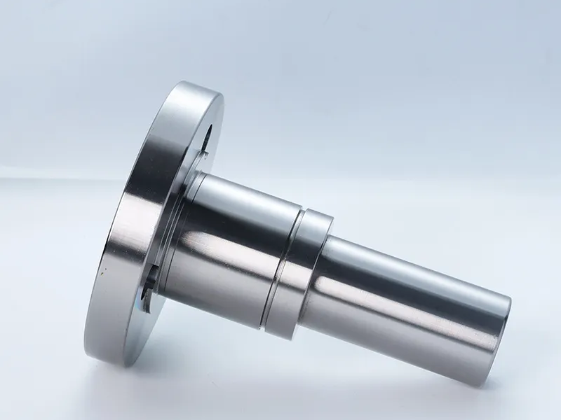
The output shaft carries reducer torque to the customer assembly.
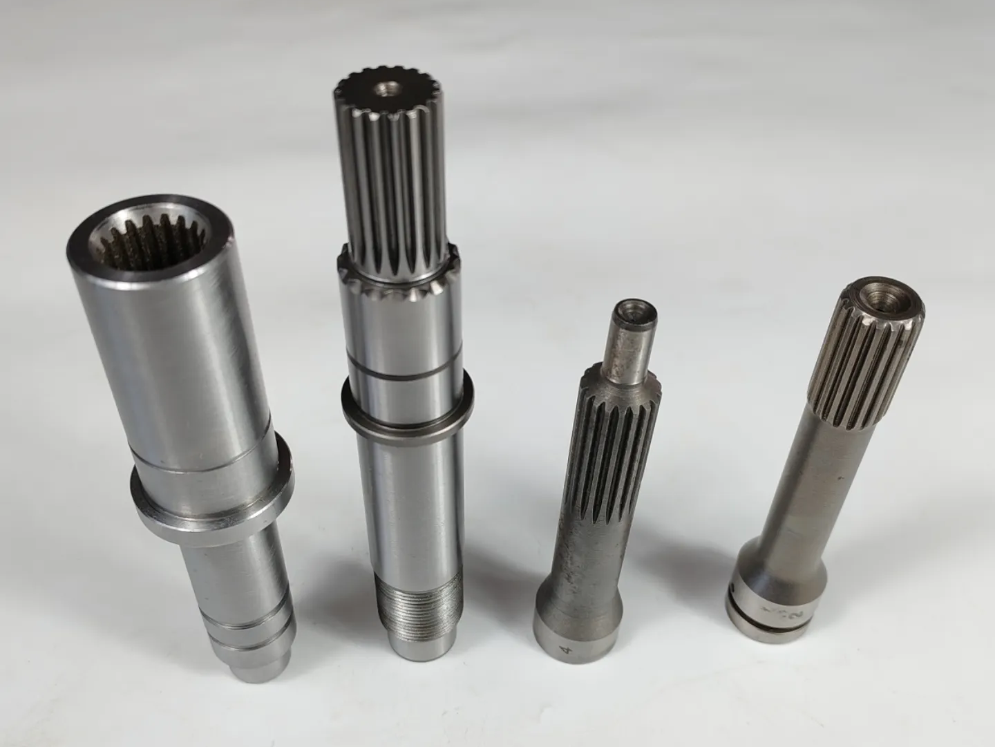
Splines connect the shaft to a mating drive component.
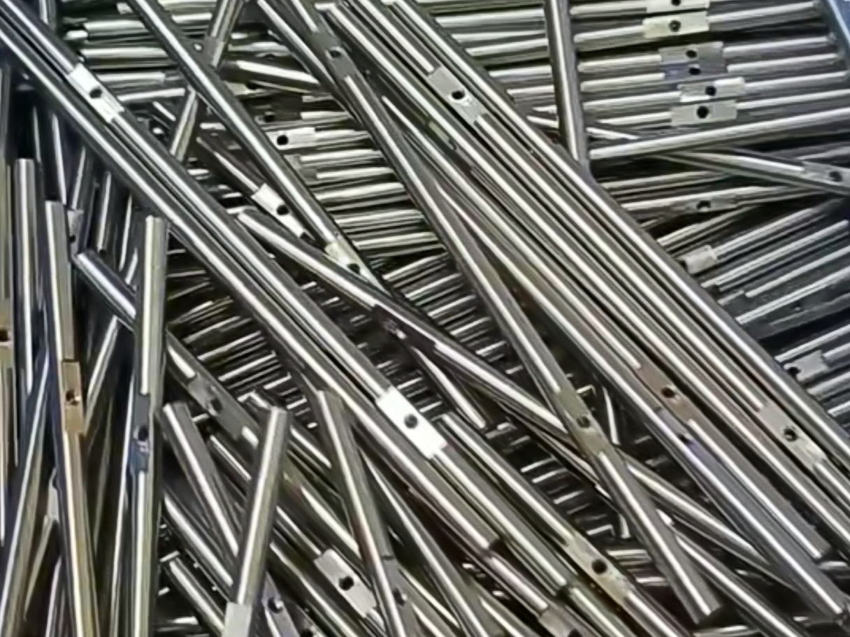
Planet pins support the gears inside a planetary reducer.
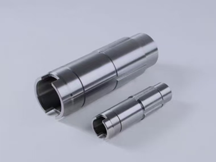
A hollow shaft provides an axial passage while carrying the reducer load.
A gear shaft may need a hard working surface while a large output shaft needs strength through its full section. We review the drawing and expected service before recommending a grade. One material is not used for every shaft.
SAE 8620 is commonly selected for shafts that will be carburized. The hardened case resists wear while the core retains useful toughness. We consider it for gear and spline features that carry contact load.
SAE 5140 can be used for general reducer shafts after heat treatment. SAE 4140 is considered when the drawing calls for greater hardenability or the part has a larger section. We review each grade separately.
SAE 52100 is a through hardening bearing steel. It can suit pins and wear surfaces that carry repeated contact stress. The required core condition and working environment must still be confirmed.
SAE 4340 provides high strength and toughness after the correct heat treatment. We consider it for large shafts and parts that carry heavy or impact loads. Section size is reviewed before the treatment condition is set.
These are common causes of rejected shafts. We address them when the setup and inspection method are planned.
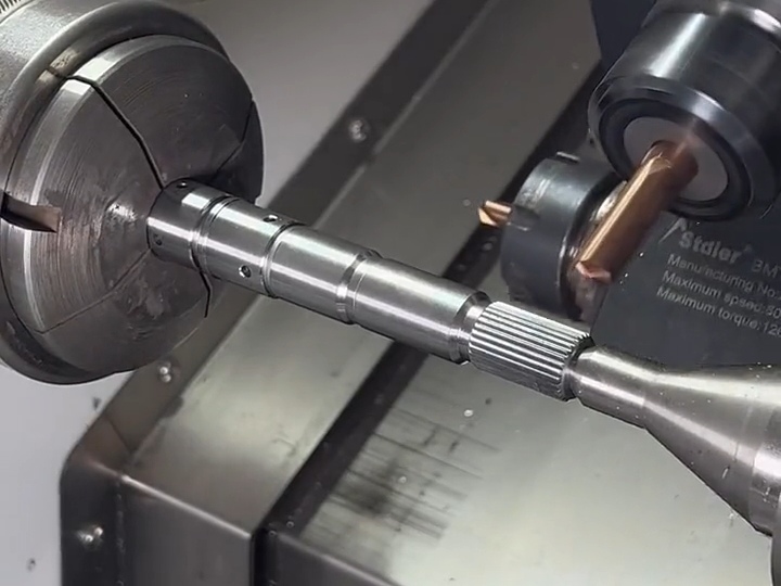
The shaft is located more than once as it moves through the shop. Each transfer can add runout. We keep the drawing datum tied to the machining setup and protect the locating surfaces until final grinding.
A correct eccentric diameter does not prove that two eccentric journals are in phase. The fixture and inspection setup use the same reference so the offset can be checked in the required angular position.
A shaft can bend or change size during heat treatment. We leave stock on surfaces that will be ground later. The remaining hardened layer is considered before any material is removed.
A thin or long shaft may look correct while it is clamped and move after release. We use lighter clamping and place support near the cut. The finished part is checked again after it is free from the fixture.
The gear datum must remain related to the bearing journals. We confirm the drawing reference before tooth cutting and use that reference again during final inspection.
We set the process after reading the drawing. A hardened journal follows a different route from a shaft that is supplied in the machined condition.
We review the current drawing before we quote the part.
Turning establishes the main shaft form and the locating surfaces.
Gear or spline features are cut from the datum agreed during review.
The approved treatment is applied before final sizing.
Grinding brings the working journals to their final size.
The finished shaft is checked against the approved drawing.
The treatment route is taken from the drawing. We confirm the treated area before allowing for movement or final stock removal.
The drawing must state the required case depth. We leave grinding stock on the journals that will be finished after hardening.
We confirm where hardness will be checked. Parts are inspected for movement after they return from treatment.
Tempering is carried out as part of the approved heat treatment route. The final condition is checked against the drawing requirement.
We first confirm that the specified material is suitable for nitriding. Surfaces that must remain untreated are identified on the drawing.
The drawing must show the area that needs local hardening. Final machining is planned around the expected change in the part.
Black oxide, phosphate coating or plating can be arranged when the drawing calls for it. Mating surfaces are reviewed before coating.
The inspection plan is prepared from the approved drawing. Checks are made during production when a result cannot be confirmed reliably after the part is finished.
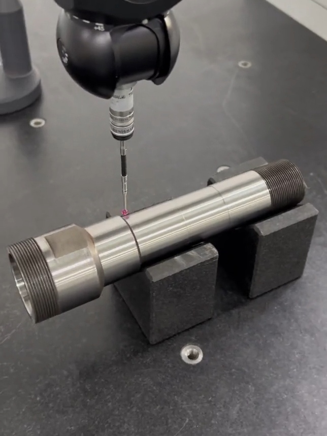
Each feature is measured from the datum shown on the drawing. The checks below are used when they apply to the part.
Journal size is measured at the locations shown on the drawing. Form and surface finish are checked when specified.
Runout is measured from the stated datum. The inspection setup follows the datum system on the drawing.
Eccentric offset is checked from the main axis. Phase is also measured when the shaft has more than one eccentric section.
Gear or spline inspection follows the parameters on the drawing. The feature is also checked against the journal datum when required.
Finished surfaces are checked for roughness where a value is specified. Burrs and handling damage are checked before packing.
Hardness is measured at the agreed location. Other treatment records are supplied when they are part of the order.
These figures show the working range of each process. We confirm the applicable range after the drawing has been reviewed.
| Machining process | Working range | Dimensional capability | Typical shaft work |
|---|---|---|---|
| Mill-Turn Machining | Bar: Ø3–80 mmChuck: up to Ø300 mm | Typical tolerance: ±0.02 mm | Stepped shafts that also need milled features or cross holes |
| Swiss Machining | Bar: Ø1–38 mmTypical length/diameter: up to 20:1 | Precision diameter: down to ±0.005 mm | Small shafts and pins with a high length-to-diameter ratio |
| CNC Grinding | Diameter: Ø2–300 mmSurface finish: down to Ra 0.1 μm | Precision size: down to ±0.003 mm | Hardened journals and bearing seats that need final size control |
Tell us what part you need and attach the current drawing.
We will review it before preparing a quote.