
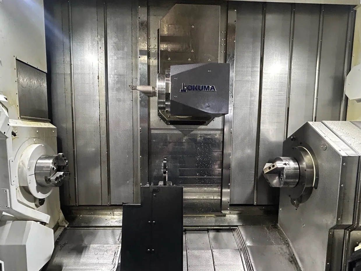
Horizontal Mill-Turn Machines
A lathe-based horizontal layout, commonly with a slant bed and a horizontal work spindle. Suited to shafts, sleeves, and other bar-fed or chuck-held rotational parts.
Get QuoteOur mill-turn machining service combines turning, live-tool milling, drilling, boring, tapping, and back working in one coordinated process for complex rotational parts. We review every drawing to match the process, workholding, tooling, and inspection plan to the part rather than forcing the design into a standard route.
We support development builds, validation lots, and repeat production with a documented process route. We combine turning and live-tool milling around a shared datum so rotational surfaces, cross holes, flats, slots, threads, and off-axis features can be completed with fewer transfers. We select spindle strategy, tooling, bar support, and operation sequence to protect concentricity while controlling cycle time and burr formation.
Choose the machine layout around the turning axis, part diameter and length, workpiece support, and milling access. Horizontal and vertical configurations combine turning and milling through different spindle and table arrangements.
A lathe-based horizontal layout, commonly with a slant bed and a horizontal work spindle. Suited to shafts, sleeves, and other bar-fed or chuck-held rotational parts.
Get Quote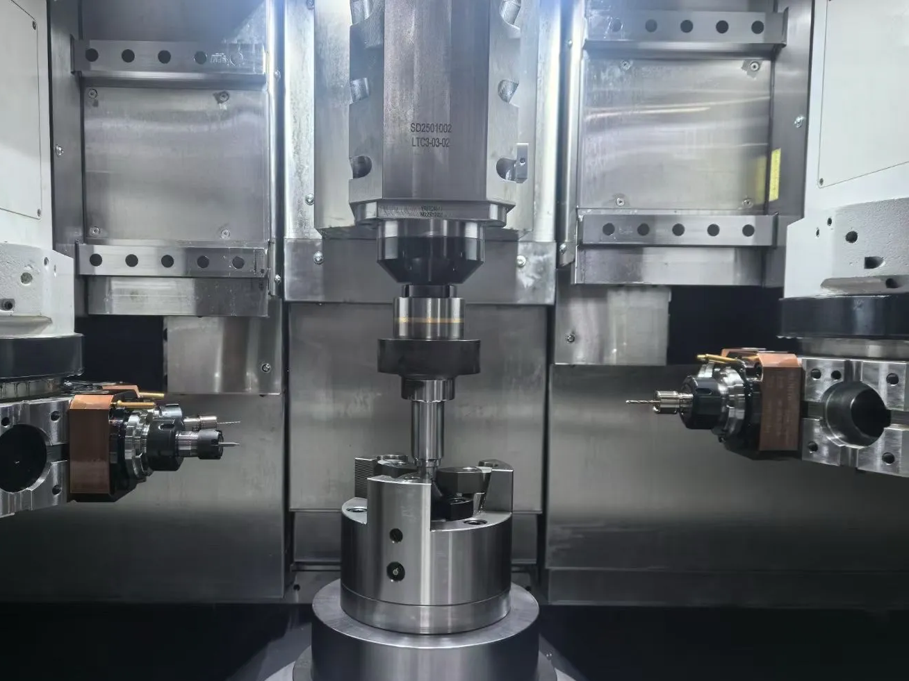
A vertical turning axis with a table-supported workpiece, in a layout derived from a vertical lathe or vertical machining center. Suited to flanges, rings, and larger-diameter housings.
Get QuoteMill-turn machining creates value when a part needs both rotational and prismatic features that must remain accurately related. We evaluate the complete process chain, not only whether one machine can perform every operation.
Turning, milling, drilling, boring, tapping, and back working can be planned as one connected process, reducing datum changes between a lathe and a machining center.
Turned diameters, sealing surfaces, cross holes, flats, and bolt patterns remain linked to the same setup logic, helping control concentricity, runout, and angular position.
Consolidating operations reduces secondary workholding, fixture manufacture, queue time, part handling, and the risk of variation introduced during re-clamping.
A coordinated sub-spindle can receive the part so cutoff faces and back-side features are machined without a separate manual setup.
Controlled workpiece speed, supported gripping, shorter process chains, and suitable milling strategies can reduce centrifugal load and repeated clamping on thin-wall or slender rotational components.
Process integration can reduce work in progress and movement between departments, which is valuable for complex prototypes, mixed batches, and repeat production with demanding delivery schedules.
One-setup capability does not remove process risk. Datum planning, spindle transfer, tool access, clamping, heat, chips, and inspection must be coordinated so integrated machining delivers a stable finished part.
We identify the functional turned datum first, then sequence milling, drilling, threading, cutoff, and back working to protect the dimensions that matter to assembly.
Pickup position, clamping length, spindle synchronization, transfer force, cutoff allowance, and back-working stock are planned to control length and concentricity.
Toolholders, turret travel, spindle noses, chuck jaws, stock, and finished geometry are checked together so driven tools can reach cross and off-axis features safely.
Jaw contact, bar support, clamping pressure, stick-out, wall thickness, and cutting load are balanced to avoid distortion while keeping the process stable.
Interrupted milling, turning heat, chip evacuation, coolant access, and tool wear are managed as one cycle so later operations are not affected by debris or thermal drift.
Probing and calibrated inspection verify critical diameters, runout, length, threads, milled-feature position, and front-to-back relationships using the drawing datum scheme.
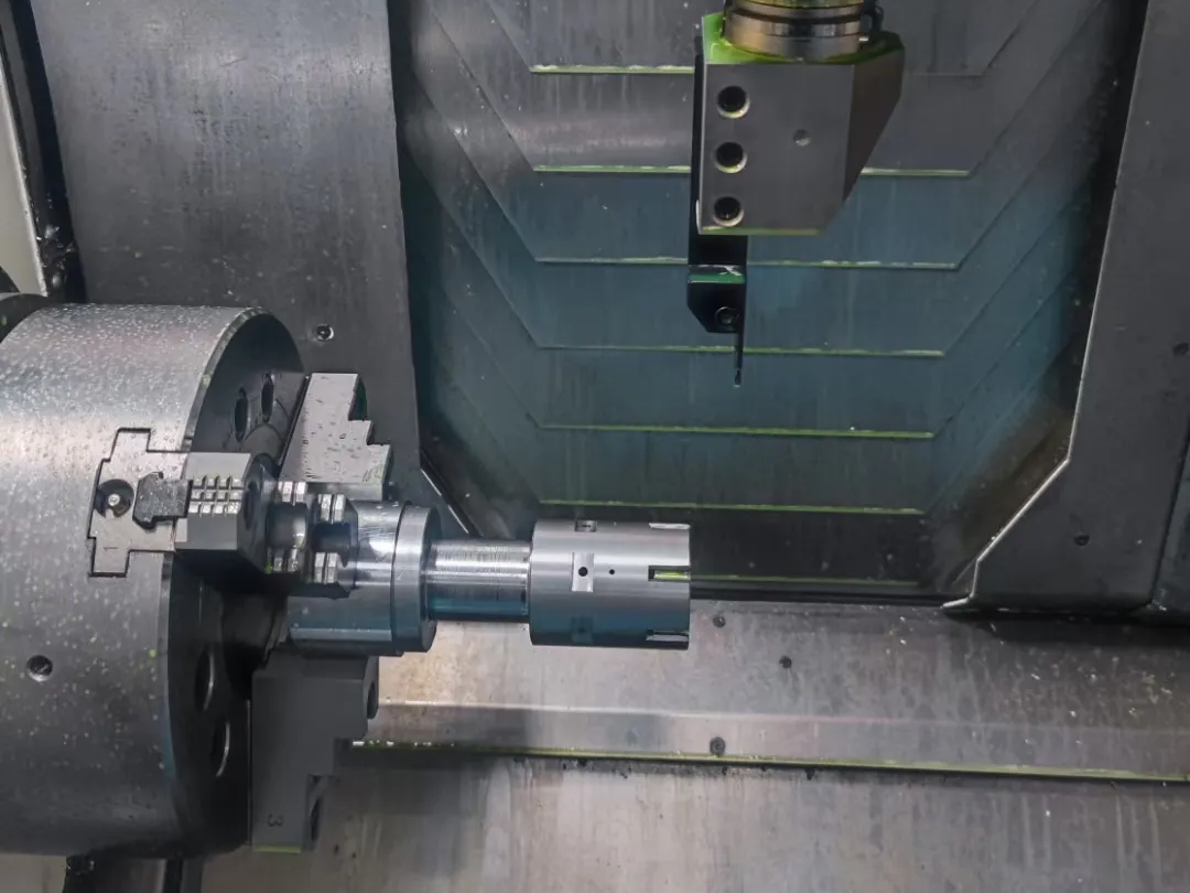
Mill-turn machining integrates servo-controlled spindle rotation with driven cutting tools and coordinated linear or rotary axes. The same machine can turn diameters, mill flats and pockets, drill or bore axial and cross holes, cut slots, and tap threads while preserving a connected datum strategy.
Machines equipped with a C-axis, live tooling, and a sub-spindle can index the part, synchronize spindle motion, and transfer it for back working. This allows many complex rotational components to be completed in one clamping cycle instead of moving between separate lathes and machining centers.
We combine turning and live-tool milling around a shared datum so rotational surfaces, cross holes, flats, slots, threads, and off-axis features can be completed with fewer transfers. We select spindle strategy, tooling, bar support, and operation sequence to protect concentricity while controlling cycle time and burr formation.
Choose mill-turn machining when a primarily rotational component also contains flats, cross holes, slots, pockets, bolt patterns, off-center features, or finished geometry on both ends. One-cycle processing is especially valuable when those features must remain aligned to turned diameters, sealing surfaces, threads, or bearing seats.
Conventional CNC turning remains more economical for simple shafts and bushings. Separate turning and milling may also suit low-volume parts with minimal secondary geometry. We compare setup count, datum relationships, main/sub-spindle handoff, live-tool access, workholding, chip control, inspection, and total production volume before choosing the route.
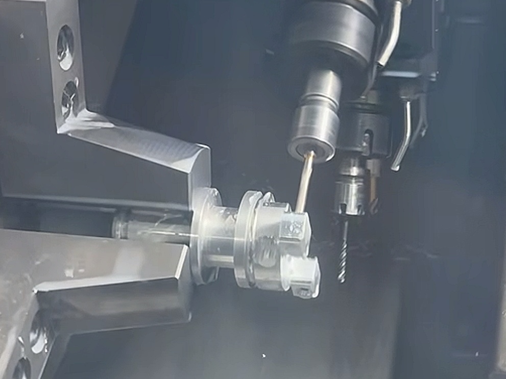
Mill-turn machining is a strong fit for parts built around an axis of rotation that also need flats, cross holes, slots, or off-axis pockets. Combining turning and milling helps preserve the relationship between cylindrical datums and secondary features.
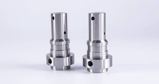
Turned steps and shoulders establish the rotational datum; live tools then add transverse bores and side features. This route reduces transfers between a lathe and a separate milling fixture.
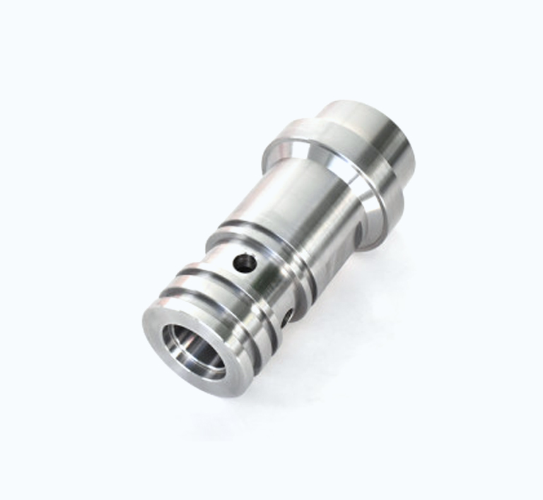
Internal bores, sealing diameters, grooves, and cross ports must remain correctly related. Turning establishes the cylindrical surfaces before coordinated milling or drilling creates the flow and locking features.
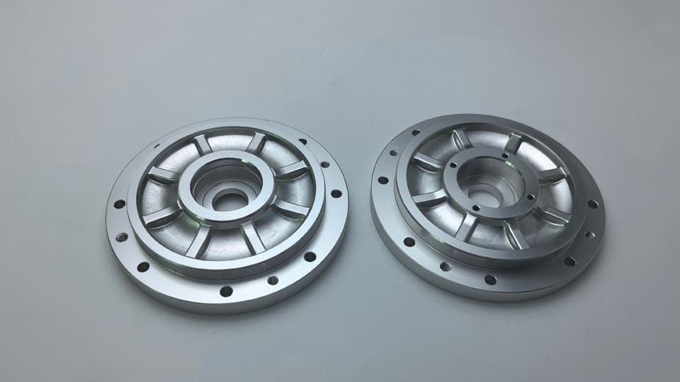
Concentric bores and outer diameters combine with face pockets and bolt patterns. A mill-turn route can preserve bore-to-flange relationships while reducing repeated workholding.
Need a similar part? Share your drawing and quantity for a manufacturing quote.
Get QuoteWe evaluate material strength, dimensional stability, tool wear, achievable finish, corrosion resistance, certification needs, and lead time together. We also review how heat, residual stress, thin walls, and any post-machining treatment may change the finished dimensions.
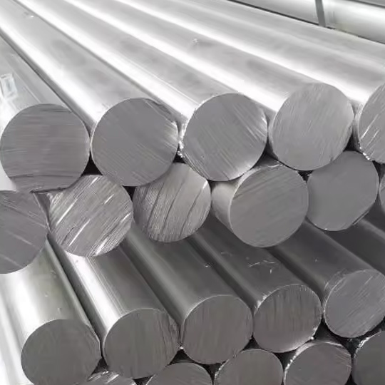
Common grades: 6061, 6082, 7075, 2024
We use 6061-T6 for many housings, cold plates, fixtures, and structural parts because it combines reliable machinability, moderate strength, corrosion resistance, and predictable anodizing response.
** Typical reference values for 6061-T6; condition, specification, temperature, and supplier data can change final properties.
View details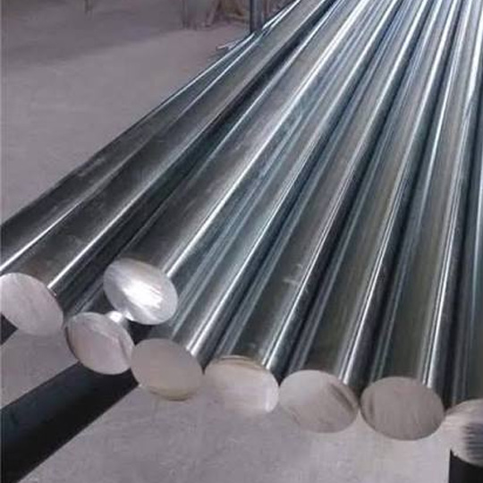
Common grades: 303, 304, 316, 316L, 17-4PH
We commonly select 304 when corrosion resistance, cleanability, weldability, and general mechanical performance are more important than the fastest cutting cycle.
** Typical reference values for 304 Stainless Steel; condition, specification, temperature, and supplier data can change final properties.
View details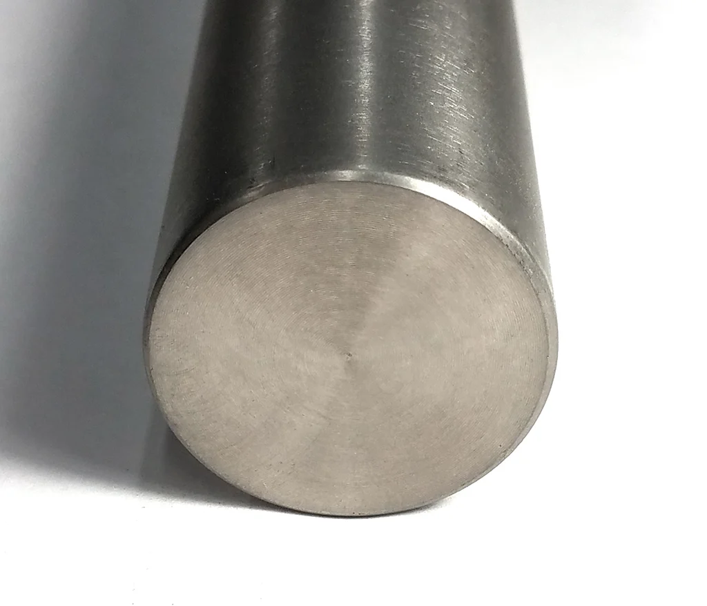
Common grades: Grade 2, Grade 5
We use Grade 5 titanium for high-strength, low-mass components. Its low thermal conductivity and springback require rigid setups, controlled tool engagement, and careful heat management.
** Typical reference values for Grade 5 / Ti-6Al-4V; condition, specification, temperature, and supplier data can change final properties.
View details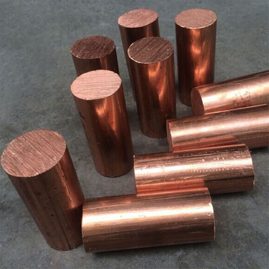
Common grades: C101, C110, C360, H59, H62
We use C360 for fittings, connector bodies, and precision hardware because it machines cleanly, supports fine threads, and provides useful conductivity and corrosion resistance.
** Typical reference values for C360 Free-Cutting Brass; condition, specification, temperature, and supplier data can change final properties.
View details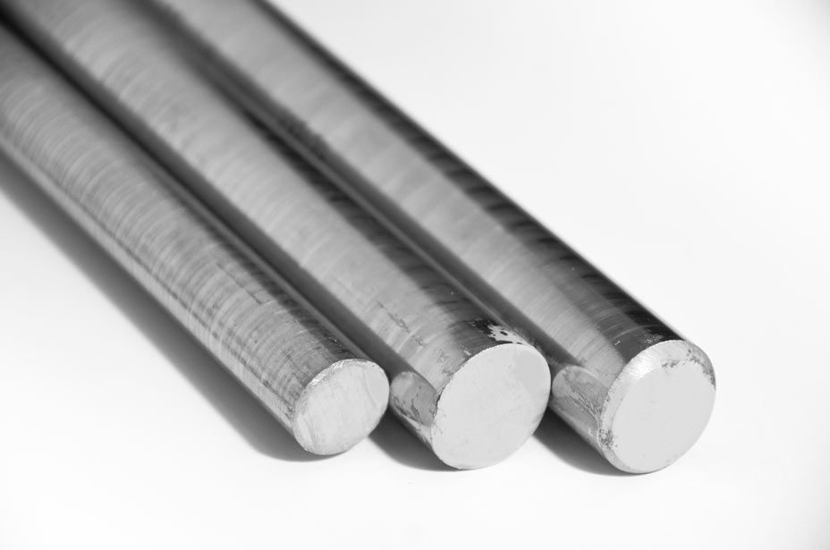
Common grades: D2, H13, A2, SKD11
We use D2 for wear components, punches, dies, and tooling that need high hardness and dimensional stability. Machining and grinding routes depend strongly on the selected heat-treatment condition.
** Typical reference values for D2 Tool Steel, Hardened; condition, specification, temperature, and supplier data can change final properties.
View details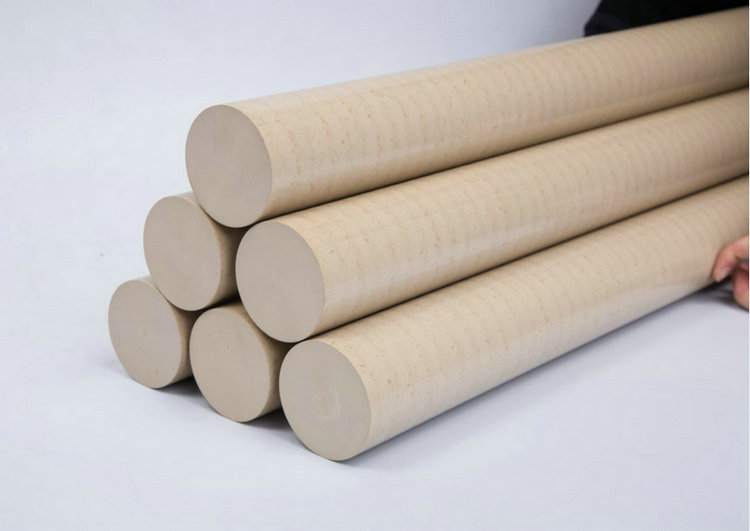
Common grades: PEEK, POM, PTFE, Nylon, PC
We use unfilled PEEK for insulating, low-mass, chemical-resistant, and high-temperature components. Tool sharpness, clamping force, heat, and moisture conditioning are controlled to limit distortion.
** Typical reference values for Unfilled PEEK; condition, specification, temperature, and supplier data can change final properties.
View detailsValues are practical reference ranges. Drawing review confirms achievable tolerance for each material, feature size, and production volume.
| Feature | Typical | Precision option |
|---|---|---|
| Turned diameter | ±0.02 mm | ±0.008 mm |
| Concentricity | 0.03 mm | 0.01 mm |
| Length | ±0.05 mm | ±0.015 mm |
| Surface finish | Ra 1.6 μm | Ra 0.4 μm |
Have critical tolerances? Send your drawing so we can review feasibility and pricing.
Get QuoteWe select finishing around corrosion resistance, wear, appearance, conductivity, cleanliness, and identification requirements. We also account for coating thickness, masking, sealing faces, and whether drawing tolerances apply before or after treatment.
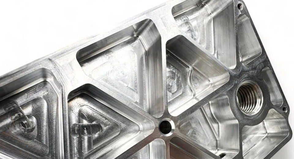
Raw machined surface with visible tool marks and feed lines, typically Ra 3.2–6.3 μm. No secondary processing means no dimensional change, lowest cost, and shortest lead time.
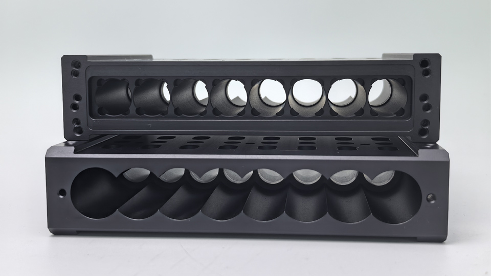
Glass beads create a uniform matte finish, masking tool marks and reducing glare. Typical roughness: Ra 1.6–3.2 μm.
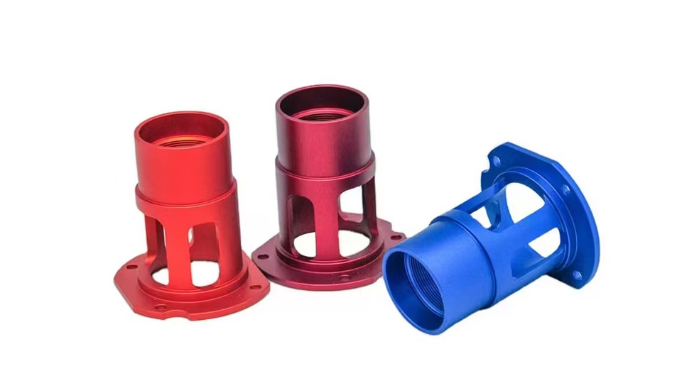
Electrolytic conversion creates a 5–25 μm porous oxide layer on aluminum. It improves corrosion resistance (200–500 hrs salt spray), reaches ~HV 300, enables color options, and provides electrical insulation with minimal dimensional change.
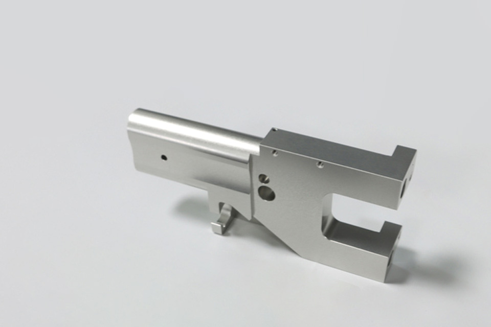
A 25–75 μm aluminum oxide layer, up to HV 500, improves wear, corrosion, and dielectric performance. The brittle film requires suitable edge radii; dimensions grow by about half the film thickness.
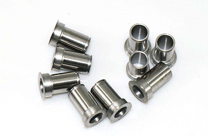
Nitric or citric acid removes free iron and restores stainless steel’s chromium oxide layer. It improves pitting resistance without adding a coating or changing dimensions.
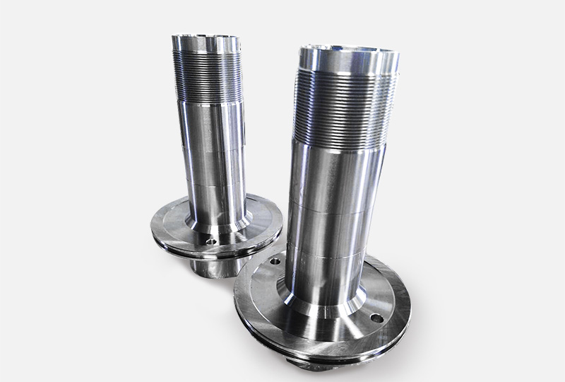
Chemical deposition creates a uniform 5–50 μm layer without edge buildup, including in bores and deep cavities. It improves corrosion and wear resistance; heat treatment can raise hardness to HV 1000.
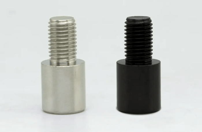
Chemical conversion forms a 0.5–1.5 μm black Fe₃O₄ film on steel. It adds a matte finish and mild corrosion protection with negligible dimensional change; oil sealing improves protection.
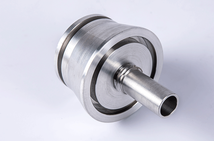
Mechanical or chemical polishing reduces roughness to Ra 0.05–0.4 μm. It lowers friction and media retention while improving cleanability and fatigue strength.
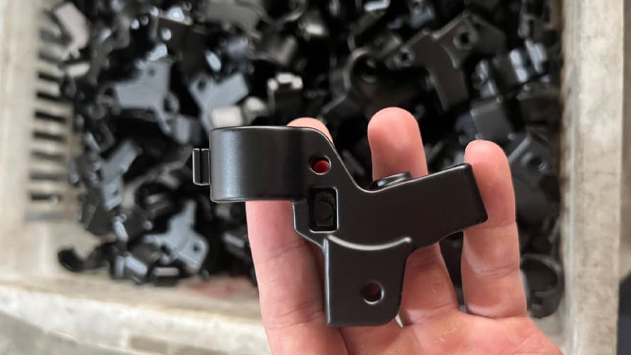
Electrostatic powder cured at 180–200°C forms a 60–120 μm non-conductive coating. It provides physical and chemical protection in many colors; threads and bores require masking.
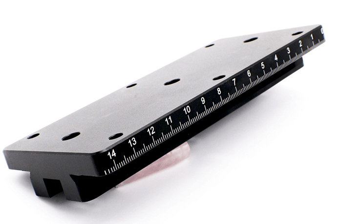
Surface oxidation or ablation creates permanent marks under 0.1 mm deep for serial numbers, QR codes, logos, and traceability. Marks resist wear and chemicals without weakening the part or affecting later processes.
We monitor critical diameters and lengths during machining and verify final form, runout, concentricity, threads, and milled-feature location with calibrated equipment. For repeat orders, we use the same datum logic and inspection plan to make batch-to-batch results easier to compare.
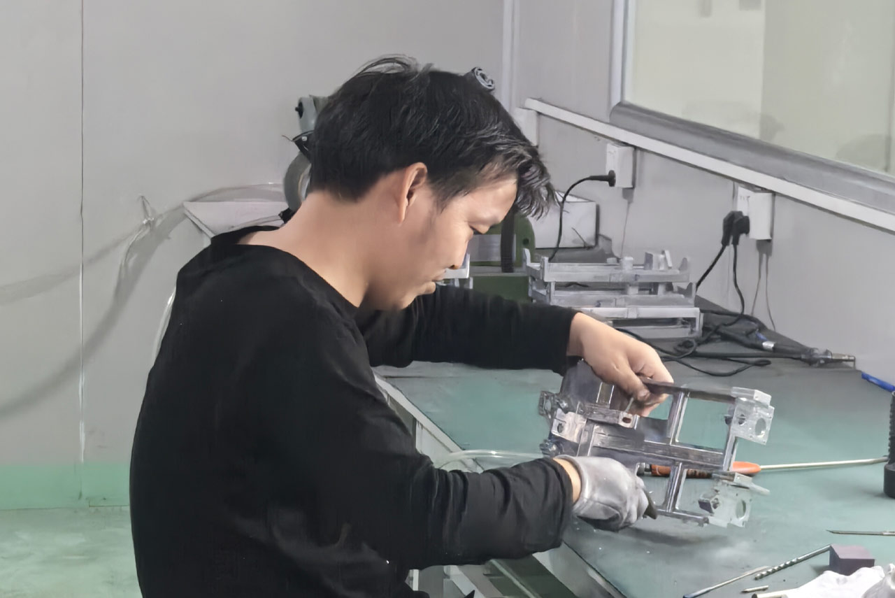
We use CMM inspection to verify datum relationships, position, profile, flatness, perpendicularity, and other geometric controls on complex parts. Measurement routines can be retained for repeat orders so we can compare results using a consistent inspection strategy.
We use digital height gauges on controlled surface plates to check step heights, hole locations, shoulders, parallel features, and datum-based dimensions. This method supports efficient in-process verification as well as final inspection of accessible features.
We verify diameters, lengths, threads, grooves, radii, runout, and feature-to-feature dimensions with calibrated micrometers, calipers, bore gauges, pin gauges, thread gauges, optical systems, and dedicated fixtures selected for the drawing requirement.
We inspect machined and finished surfaces for burrs, scratches, dents, contamination, coating consistency, color variation, marking quality, and protected critical faces. Approved samples and drawing notes guide cosmetic acceptance when appearance matters.
Need inspection reports or material certificates? Include your requirements when requesting a quote.
Get QuoteOur mill-turn work is used in fluid control, motion systems, medical instruments, semiconductor equipment, and industrial automation. We focus on the feature relationships that matter in use, including shaft alignment, sealing integrity, balanced rotation, connector fit, and repeatable assembly.
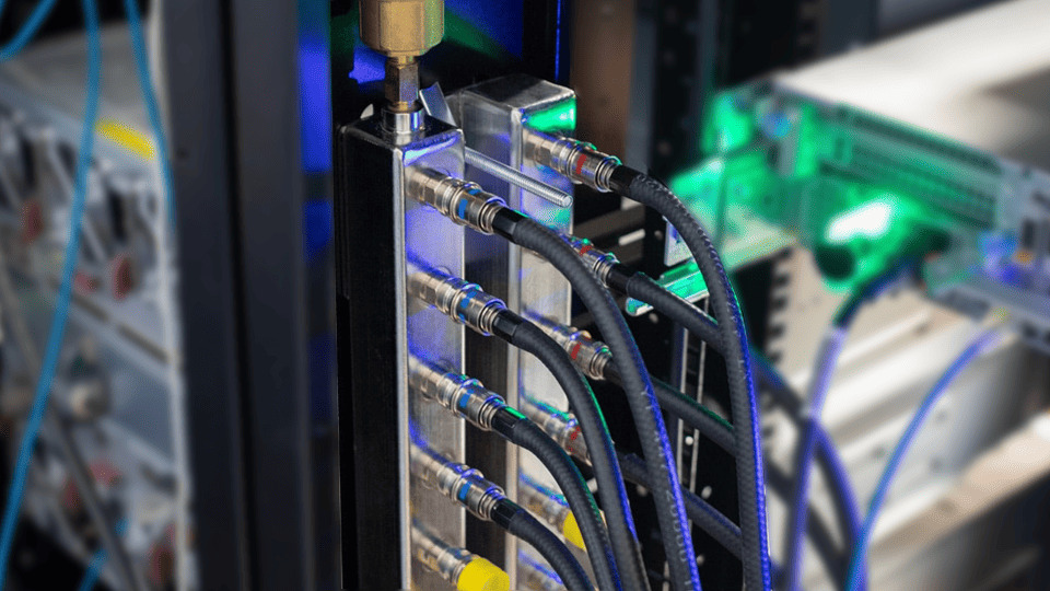
We manufacture valve bodies, fittings, manifolds, and sealing interfaces designed around controlled flow, pressure integrity, and reliable connection geometry.
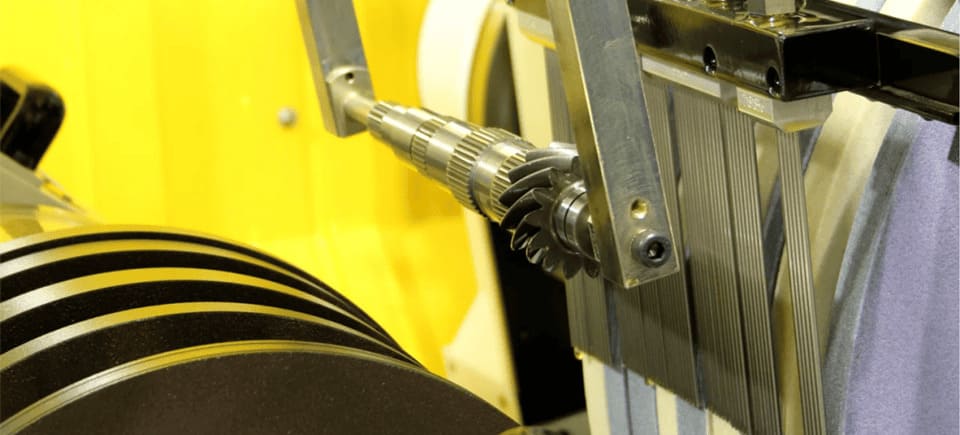
We produce shafts, bearing features, couplings, and actuator components where concentricity, runout, and mating dimensions influence movement quality.
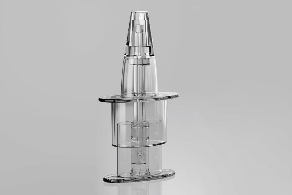
We machine instrument bodies, precision shafts, fittings, and device components with close attention to cleanability, edge condition, and dimensional verification.
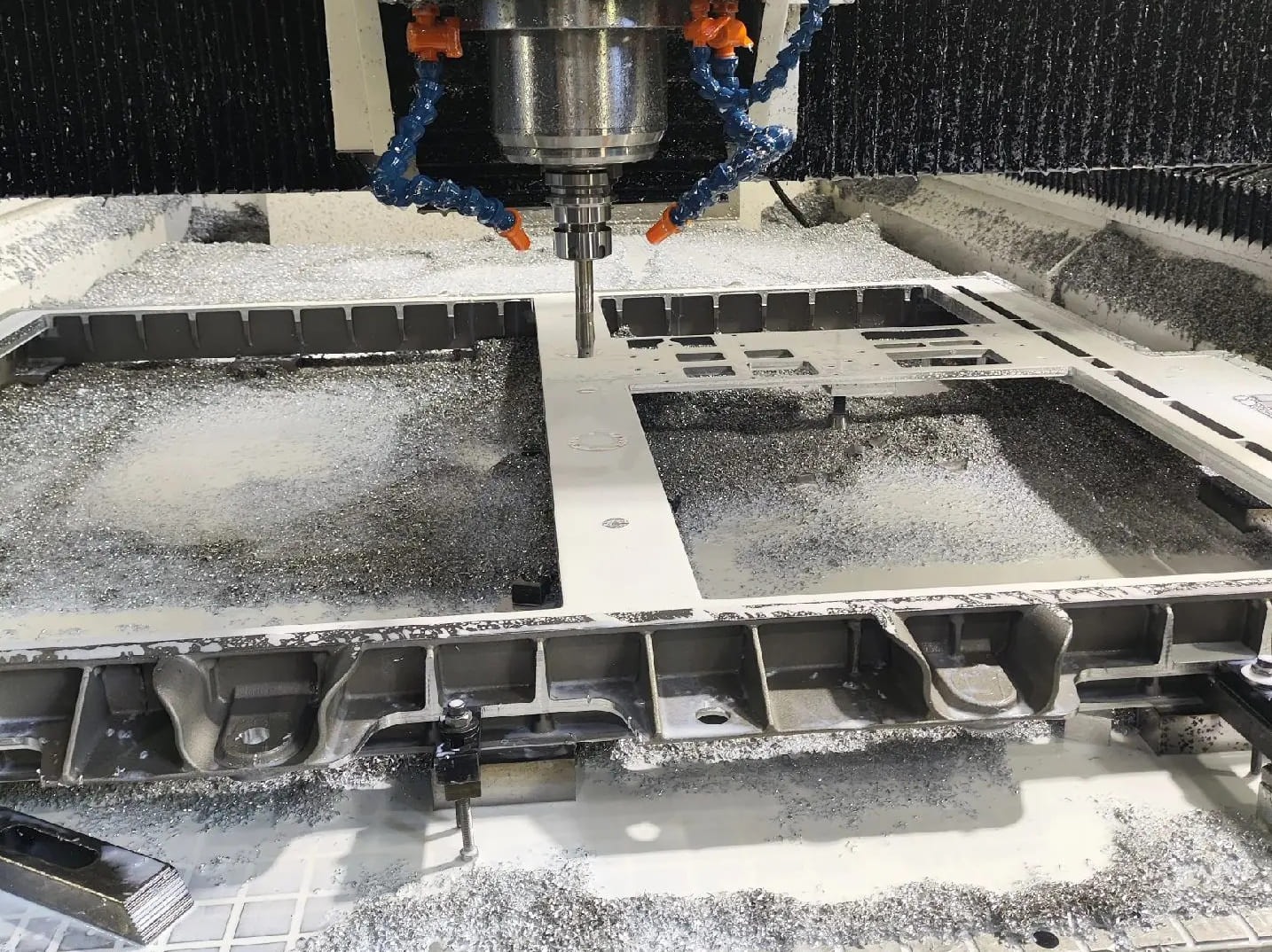
We manufacture precision components for automotive powertrain with process planning and inspection matched to functional requirements.
We combine early DFM feedback, controlled production, and drawing-based inspection so our customers receive practical answers before material is committed and traceable results after machining is complete.
DFM feedback identifies tolerance, tool access, material, and finishing risks before production.
Machining, secondary operations, inspection, and delivery are coordinated through one project team.
Documented setups and inspection plans support repeat orders from pilot runs through stable production.
These answers cover the process questions that most often affect design review, quotation, and manufacturing route selection.
Mill-turn machining combines CNC turning with live-tool milling, drilling, boring, tapping, and other operations in one machine. Servo spindle control allows the workpiece to rotate for turning or index as a controlled C-axis while driven tools machine flats, holes, slots, and off-center features.
A standard CNC lathe is optimized for rotational geometry such as diameters, grooves, tapers, and threads. A mill-turn machine adds driven tools and coordinated axes for milled and drilled features. Machines with a sub-spindle can also complete the rear of the part in the same automated cycle.
Strong candidates are rotational components that also contain cross holes, flats, keyways, slots, pockets, bolt patterns, off-axis bores, or features on both ends. Examples include valve bodies, manifolds, fittings, drive shafts, sensor housings, connectors, and medical instrument components.
Not automatically. It can reduce setup and datum-transfer error, but the result still depends on workholding, spindle transfer, machine capability, tooling, thermal stability, programming, and inspection. Simple turned parts or very low-volume parts with one secondary feature may cost less on separate machines.
Send a 3D CAD model and a 2D drawing with material, quantity, critical tolerances, datum references, surface finish, thread specifications, heat treatment, and inspection requirements. Annual volume and batch size help us compare bar-fed, chuck-based, one-cycle, and split-process production routes.
Send us your drawing, material, quantity, and quality requirements.
We’ll help define the next step.