
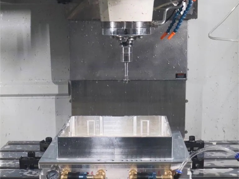
In-House Housing Machining
CNC turning, milling and turn-mill machining cover round bodies, pocketed enclosures and housings with features on several faces. We choose the setups to keep the assembly datums consistent.
We machine housings from customer drawings, from pocketed enclosures to round bodies with precision bearing seats. Turning, milling and turn-mill machining are completed in-house. Where required, we finish-machine blanks from partner foundries and coordinate treatment and specified leak testing.
Request a Drawing-Based Review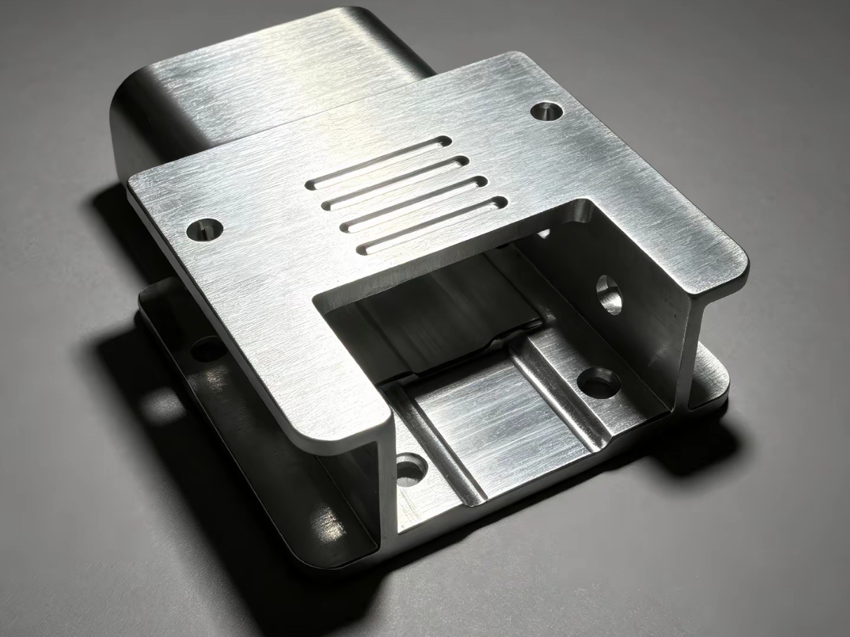
We make custom housings for prototypes and repeat production, from billet-machined enclosures to finish-machined castings. Your drawing defines the bearing seats, cavities and sealing interfaces. We plan the machining route around those features and coordinate the specified treatment and inspection before delivery.
CNC turning, milling and turn-mill machining cover round bodies, pocketed enclosures and housings with features on several faces. We choose the setups to keep the assembly datums consistent.
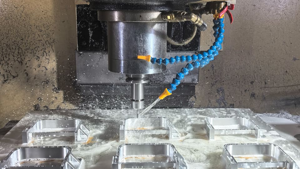
We machine from solid stock or finish blanks supplied by partner foundries. Required heat treatment and surface finishing are scheduled with machining allowance and masking agreed before production.
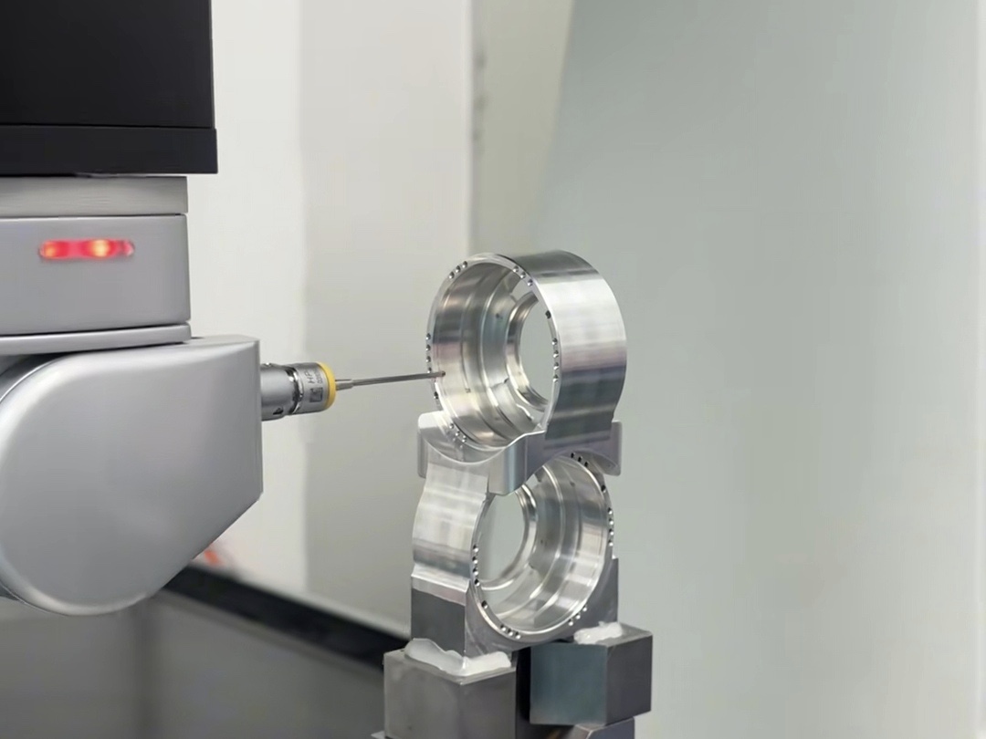
We check the specified bearing fits, mounting geometry and sealing surfaces against the drawing. CMM reports and leak testing are included when agreed, with the test method and acceptance criteria defined in advance.
The housing structure determines where a fixture can grip and how the tool can reach the internal features. We review the complete model, including the mating cover and fasteners where available.
Upper and lower shells close around the assembly. We machine the parting faces, locating features and fastener pattern so the halves can be assembled without forcing them into alignment.
Internal cavities are machined from billet or a suitable casting. Pocket depth, wall thickness and internal corner radii are reviewed for cutter access before roughing begins.
Covers and end caps carry gasket faces or O-ring grooves. The inspection plan identifies sealing-face flatness, groove geometry and the mating interface.
Mounting flanges, bolt circles and register pilots locate the housing on the machine. Hole position and the relationship between the pilot and bearing bore are checked from the drawing datum.
The halves are located and fastened in the specified assembly condition before matched machining or line boring. The finished bore is checked in that condition.
Deep cavities and thin sections need support near the cut. Clamping pressure and stock removal are controlled, and critical surfaces are checked after the fixture is released.
We plan the operations together before choosing the first setup. Turn-mill machining can reduce transfers on suitable round housings; pocketed parts may need a milling route with dedicated support.
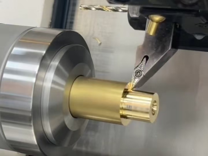
Round bodies, bearing seats, seal bores and threaded rings are machined from consistent rotational datums.
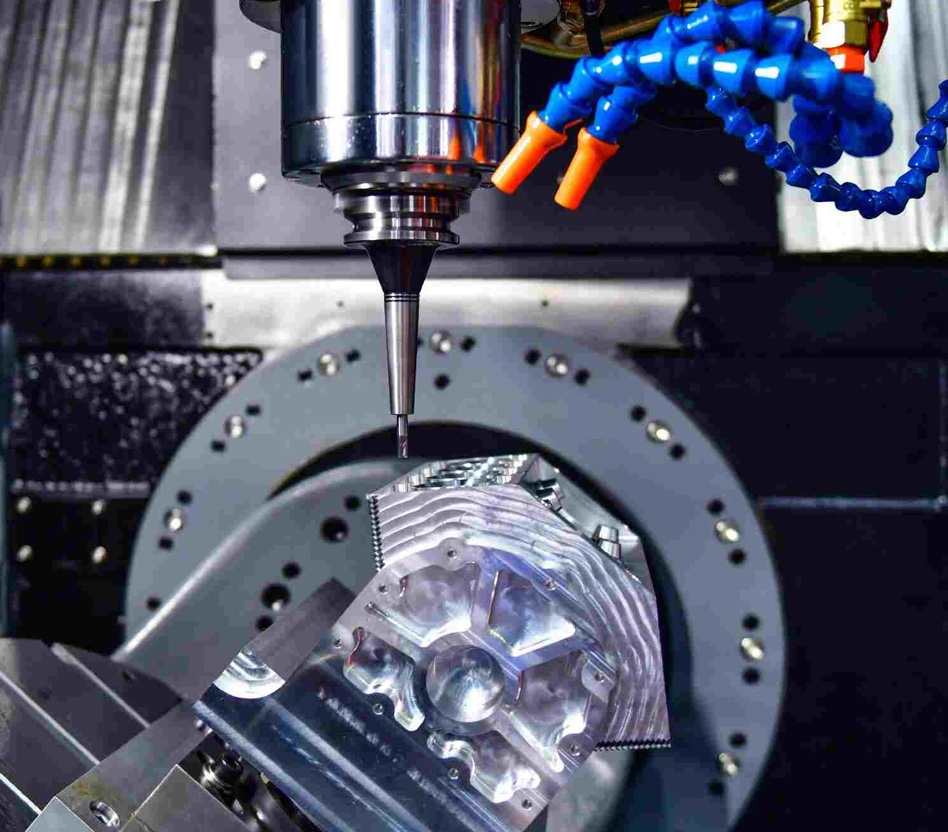
Cavities, mounting faces and multi-face hole patterns are milled with fixtures that support the part without loading thin walls.
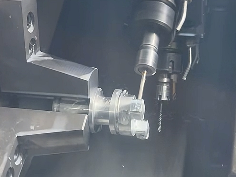
A rotational body with flats, cross holes or ports may be completed in fewer setups to preserve the relationship between features.
We establish the datums before roughing and retain finishing stock for surfaces that may move during treatment. The sequence is reviewed against the housing drawing before machining starts.
Review the design datums and machine stable locating faces. The same references are carried into later setups wherever the drawing allows.
Remove bulk stock from cavities and external surfaces. Rough-bore the main seats and leave controlled finishing allowance.
Where treatment is specified, schedule it before final sizing. Check movement and confirm that enough allowance remains to recover the required geometry.
Drill mounting holes and thread pilot holes. Complete accessible ports and other details before finishing vulnerable seats or sealing faces.
Finish-bore the bearing seats and finish the joint faces. Tapping, spot-facing and other remaining features follow the approved route.
Deburr, clean and inspect the part. Complete the agreed coating and leak-test sequence, protecting critical fits during handling.
We review the tolerances on your drawing for both machining and measurement access. Thin walls, long bore spans and intersecting features require a setup plan before a tolerance can be confirmed. The drawing identifies the applicable standard and datum references. Bore center distance is checked separately as a drawing dimension.
Bolt circles, ports and cross holes
Check feature locations from the assembly datums so fasteners and fittings align.
Rotating bore sections and seal seats
Check the specified variation at each measured section relative to the datum axis.
Bearing seats and shaft bores
Check the complete specified surface relative to the datum axis as the part rotates.
Parallel shaft bores
Measure the orientation of each specified bore axis relative to the drawing datum.
Parting faces, sealing faces and mounting bases
Check the surfaces that support the gasket or locate the housing.
Bore axes relative to mounting faces
Verify the orientation needed for the cover and internal assembly.
Bearing seats and spool bores
Check the roundness of individual cross-sections separately from bore diameter.
Precision cylindrical bores
Check the form of the complete cylindrical surface where the drawing specifies it.
Complex cavities and sealing contours
Compare the required surface with the nominal model using an accessible measurement method.
The material grade and condition come from the drawing. For aluminum housings, we also review the specified temper and whether the order calls for billet or a finish-machined casting.
| Material | Typical housing use |
|---|---|
| Aluminum 6061-T6 | General robot, motor and instrument housings. |
| Aluminum 7075-T6 | Housings with a specified higher strength requirement. |
| Die-cast aluminum ADC12 or A380 | Production castings with finish-machined bores and sealing faces. Grades are selected to the specified standard. |
| Stainless steel 303, 304 or 316L | Corrosion-resistant enclosures selected to suit the service environment. |
| Stainless steel 17-4 PH | Higher-strength stainless housings with a defined heat-treatment condition. |
| Grade 45 steel or 4140 | Load-bearing bodies and gearbox housings where the drawing specifies steel. |
| Brass or copper alloys | Small housings requiring the specified conductivity or corrosion resistance. |
| POM or PEEK | Non-metallic enclosures where the drawing specifies an engineering plastic. |
** Material examples are for drawing review. Grade, temper, casting quality and any permitted substitution must be confirmed for the order.
We set the machining allowance and inspection sequence before treatment. The order must identify the surfaces to be protected and whether acceptance dimensions apply before or after finishing.
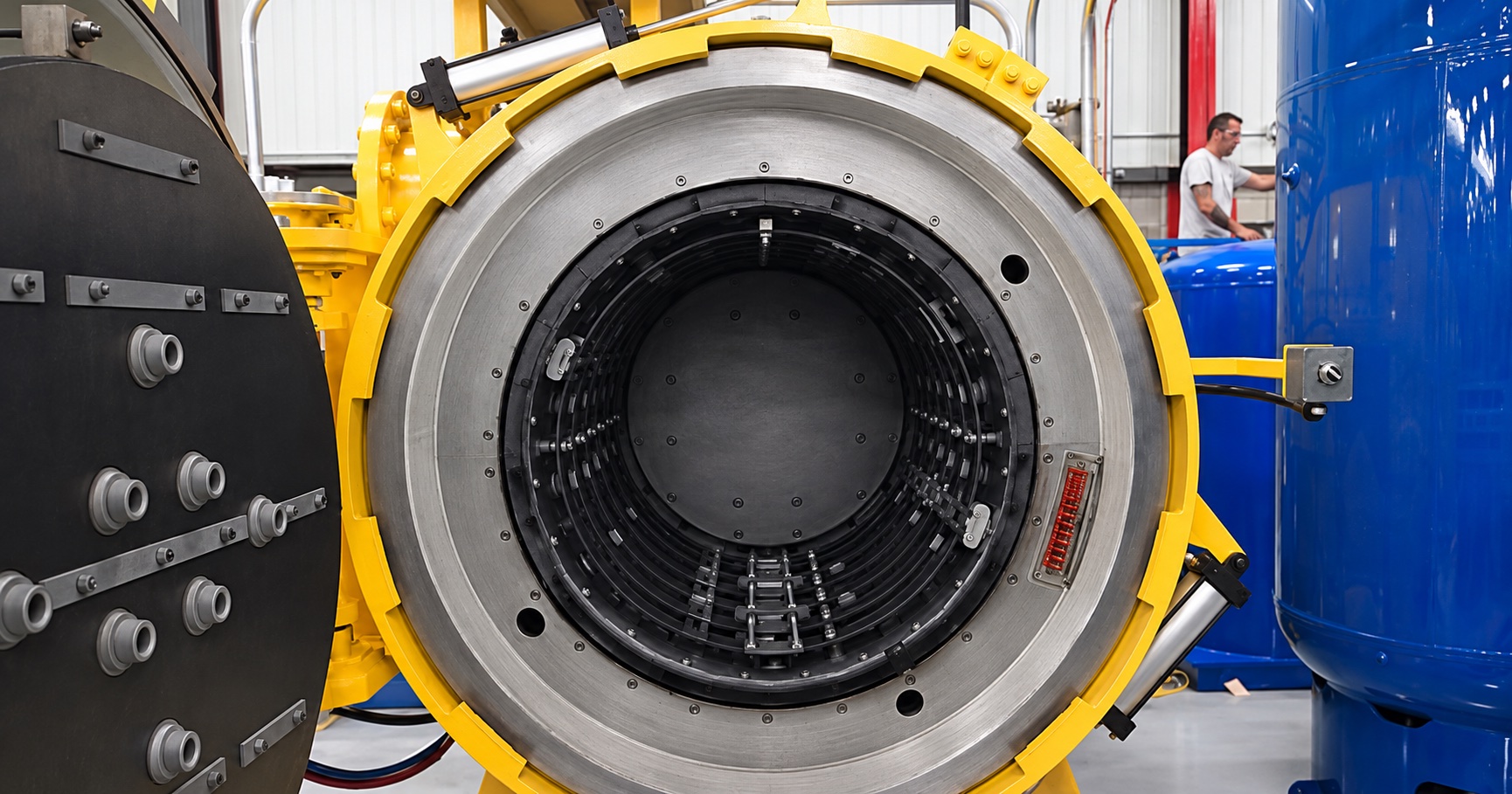
Specified stress relief, aluminum solution treatment and aging, or steel hardening are coordinated through qualified partners. Treatment is scheduled around the material condition and the risk of movement.
We check the blank after treatment before finishing bearing seats and sealing faces.
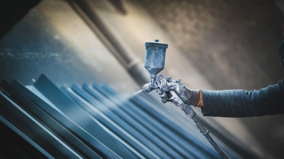
Options include bead blasting, anodizing, electroless nickel plating, stainless passivation and specified paint or powder coating. Fits, threads and sealing surfaces receive the agreed masking.
Coating growth is accounted for when setting the machining size of a critical interface. Review our surface finishing options.
Chips and cutting oil are removed from cavities and passages. Hole exits and edges are deburred so they do not interfere with assembly or damage a seal. The inspection report follows the drawing datums.
Required records are agreed during quality planning.
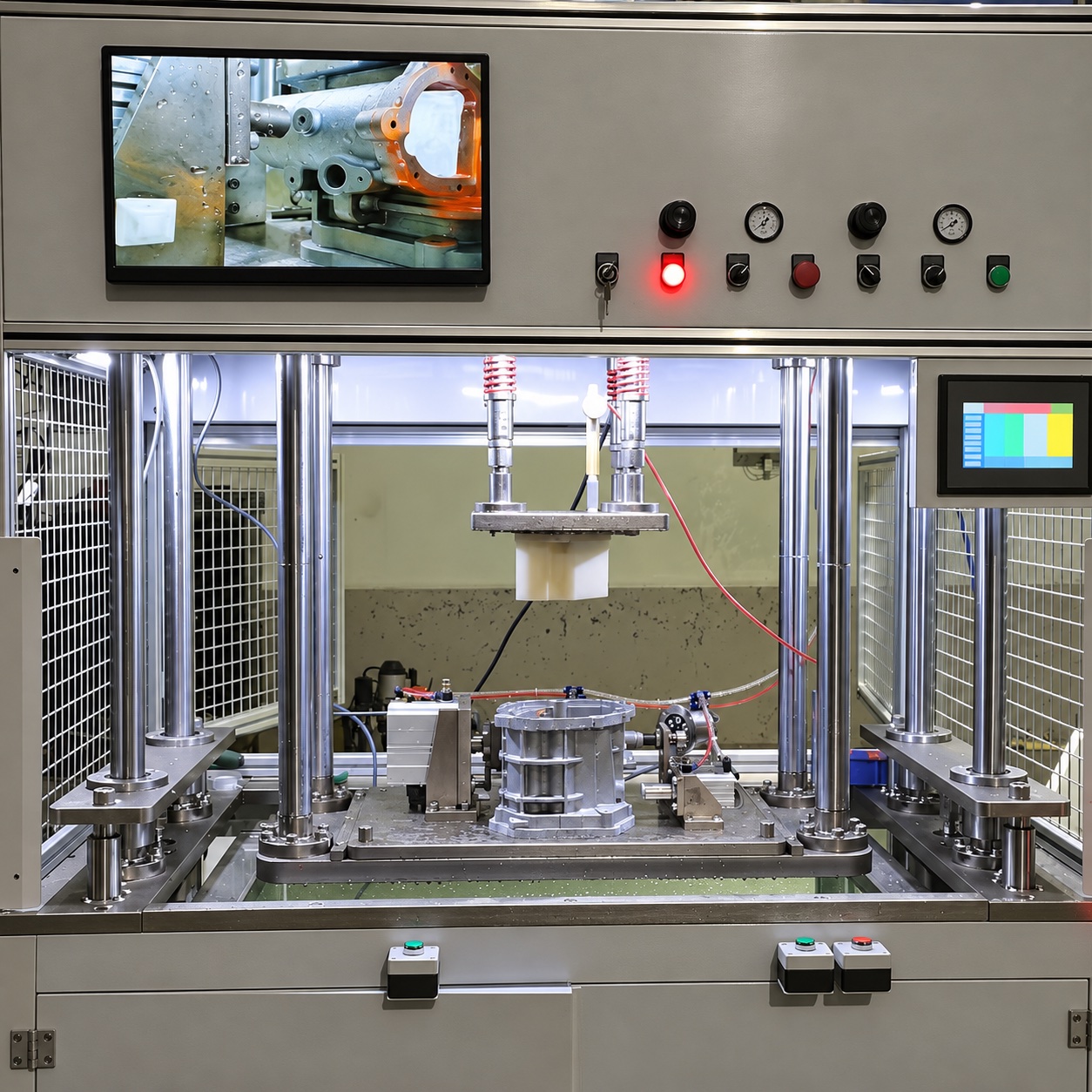
Air leakage, pressure-decay, water immersion or helium testing can be included in the agreed scope. The test method, pressure, preparation and acceptance criterion must be defined before production.
A machined sealing face alone does not guarantee a waterproof assembly. Seal selection, cover stiffness and fastener torque also affect the result. An IP target requires the corresponding agreed test.
We review the features that locate the internal components and connect the housing to the rest of the equipment.
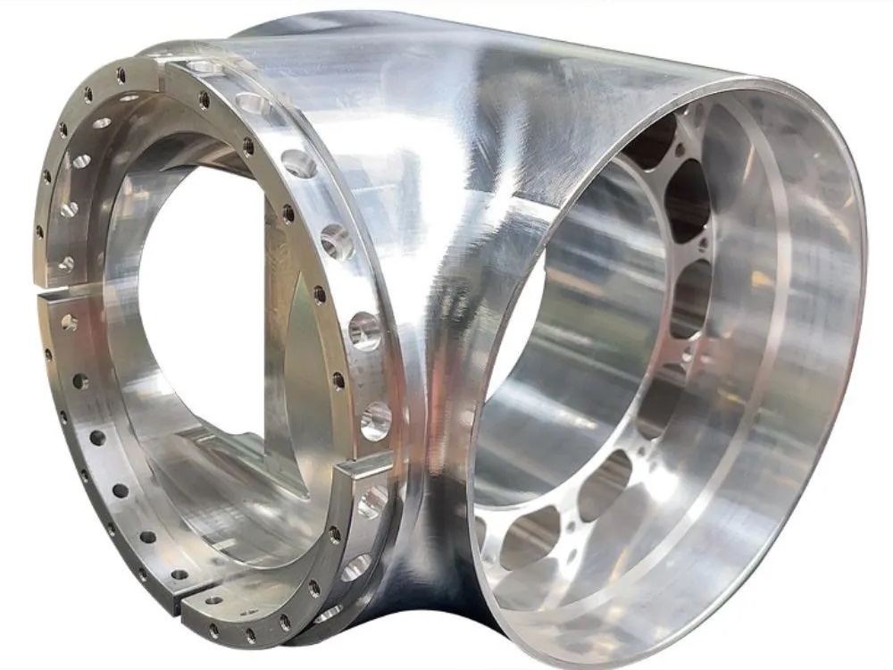
Bearing seats, encoder mounts and cable passages are located from the joint assembly datums.
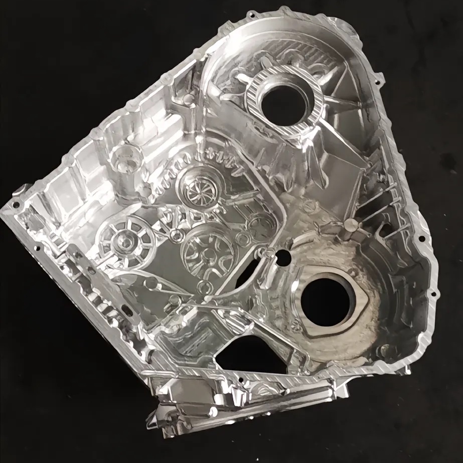
Shaft bore position and center distance are controlled to maintain the designed gear relationship.
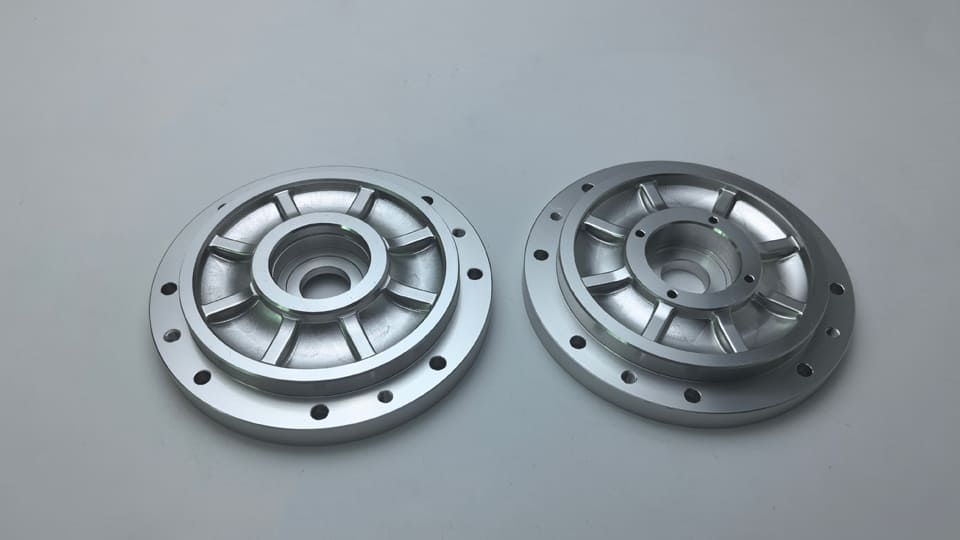
Stator bores, end-cover interfaces and mounting pilots are machined to the required axis relationship.
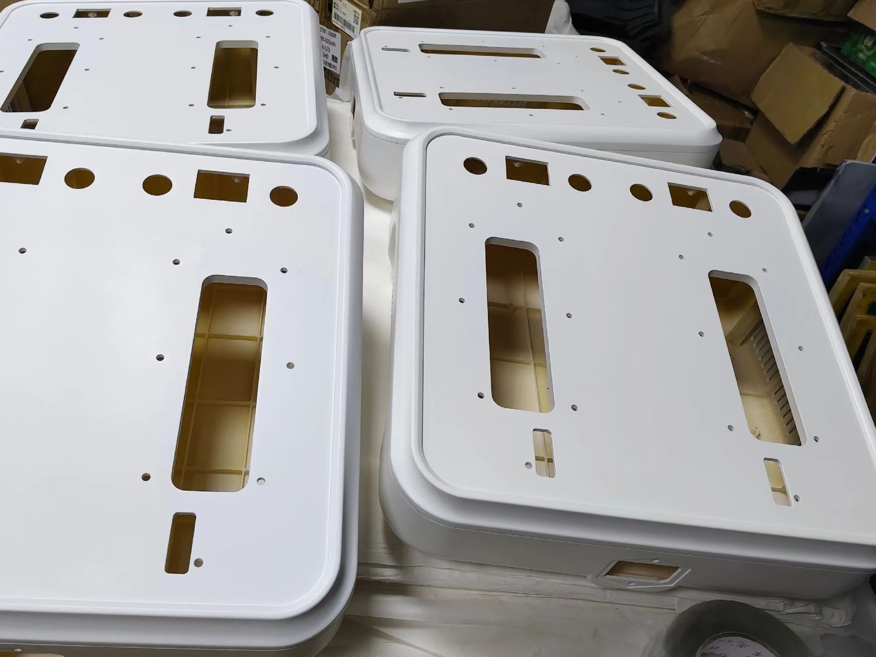
Cosmetic acceptance, cleaning and documentation requirements are reviewed alongside the drawing dimensions.
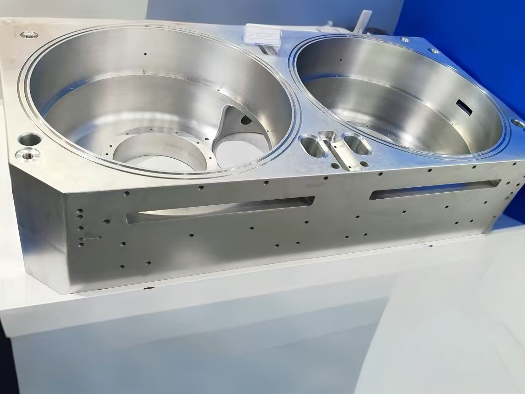
Sealing surfaces and handling requirements are defined before machining. Cleanliness acceptance is specified separately.
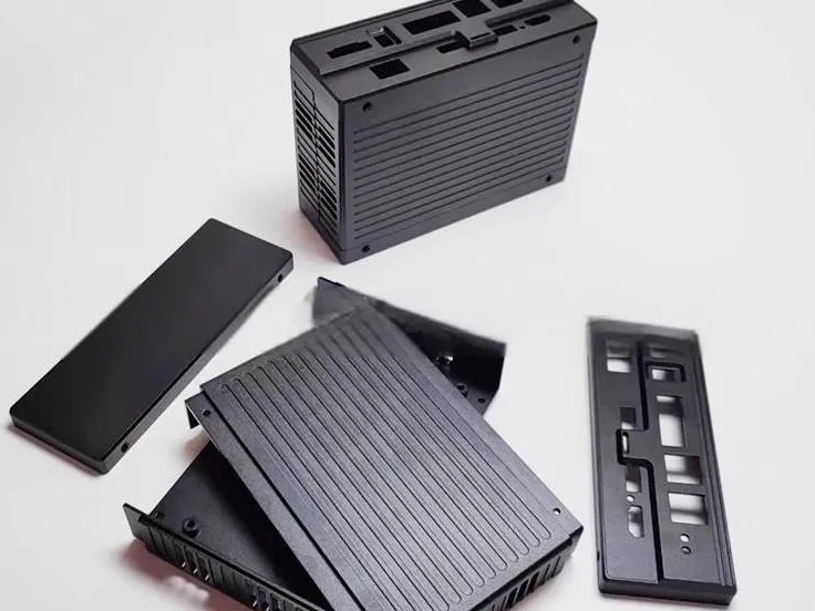
Connector openings, cover interfaces and mounting faces are machined for communications equipment. The drawing defines the enclosure fit and the surfaces that must remain protected during finishing.
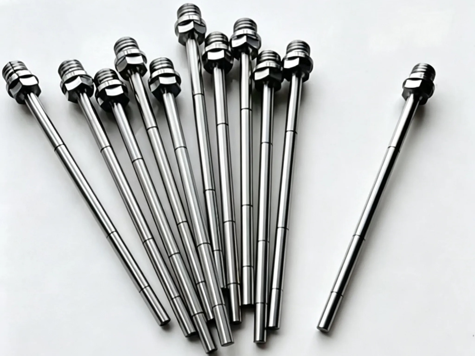
Tubular bodies and threaded connections are machined for sensor assemblies. Bore size, wall thickness and sealing interfaces are checked against the drawing.
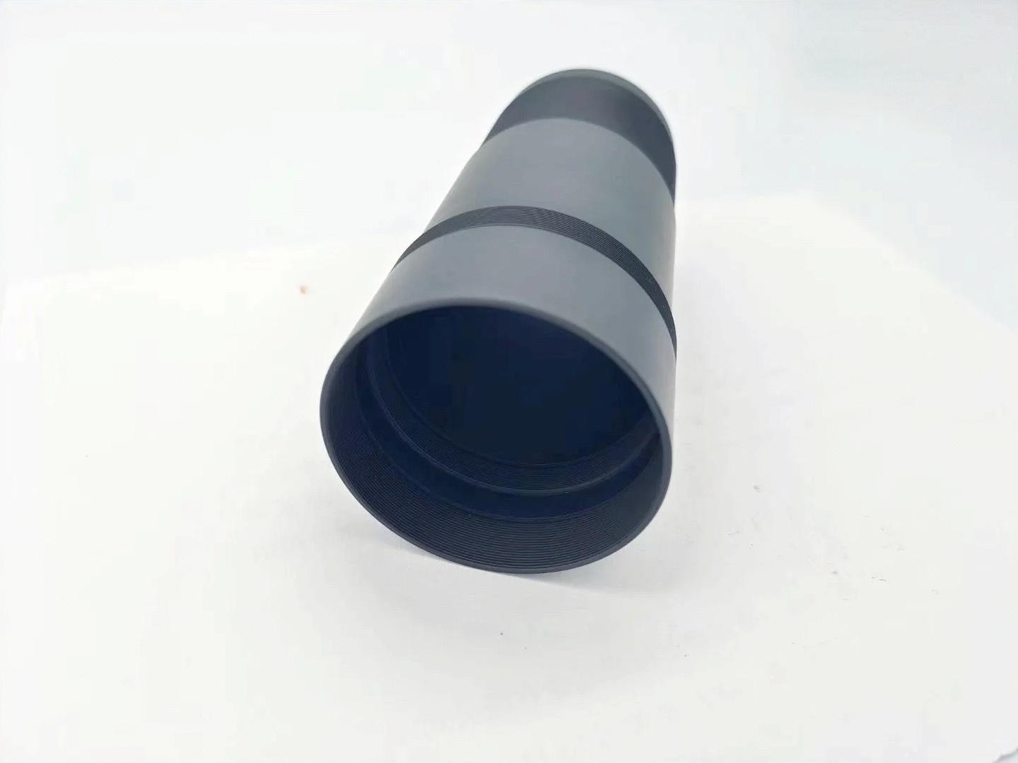
Lens seats, internal threads and locating diameters are machined from the specified datums. The drawing defines the surface finish and coating requirements for internal optical interfaces.
Send your drawing and order quantity. We will review the machining route, critical interfaces and any specified test requirements before quoting.
Request a Drawing ReviewTell us what part you need and attach the current drawing.
We will review it before preparing a quote.