Upload CAD & Define Requirements
Provide the STEP model, drawing, target vacuum level, leak-rate requirement, flange standard, material and critical tolerances.
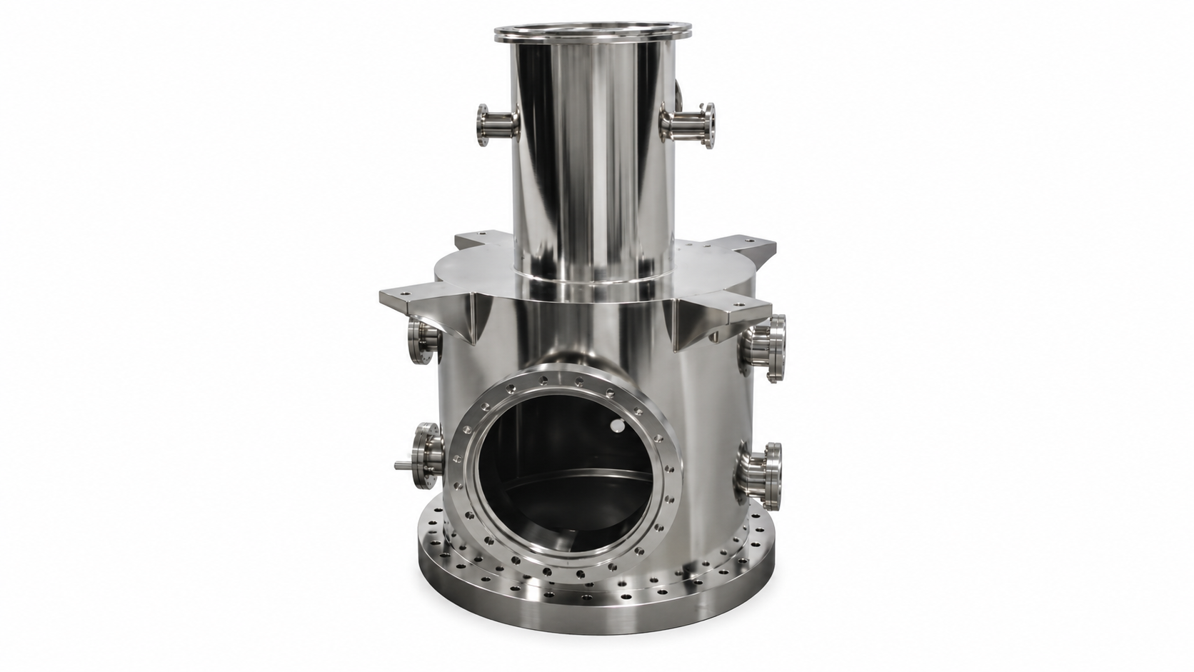
A vacuum chamber is not simply a welded enclosure. Chamber performance depends on structural stability, flange geometry, CNC accuracy, weld integrity, cleanliness, outgassing control and final vacuum verification working together.
Provide the STEP model, drawing, target vacuum level, leak-rate requirement, flange standard, material and critical tolerances.
Plan the vacuum boundary, machine critical features, control welding distortion and reserve sealing-critical surfaces for post-weld finishing where needed.
Complete dimensional inspection, surface cleaning, weld verification, helium leak testing and pump-down checks according to the project specification.
Every weld, flange, threaded hole, internal cavity and surface can affect pump-down time, leak tightness, cleanliness and final equipment performance.
Review wall thickness, panel deflection, port reinforcement, vacuum conductance and trapped-volume risks before fabrication begins.
Machine sealing faces, O-ring grooves, ports and datums, then control TIG/GTAW welding sequence and post-weld distortion.
Control residues and outgassing sources, verify geometry, inspect welds and validate chamber integrity with helium leak testing.
304L and 316L stainless steels remain common choices, while aluminum is attractive for low weight, high thermal conductivity and highly machined chamber designs.
| Material | Why It Is Used | Typical Considerations |
|---|---|---|
| 304L Stainless Steel | Good weldability, corrosion resistance and mechanical strength; compatible with polishing and vacuum bakeout. | Widely used for high-vacuum chambers, PVD systems, research equipment and general industrial vacuum systems. |
| 316L / 316LN Stainless Steel | Improved corrosion resistance in certain chemical environments. | Useful where process gases, cleaning chemistry, magnetic requirements or UHV duty justify the additional cost. |
| 6061 Aluminum | Low weight, good thermal conductivity and excellent machinability. | Well suited to machined chambers and structural components; welded designs require careful HAZ, oxide and distortion control. |
| 5xxx / 6xxx Aluminum | Common weldable aluminum families for fabricated chambers. | Appropriate grade selection depends on strength, corrosion, welding and heat-treatment requirements. |
| Titanium / Specialty Alloys | Selected for unusual mass, corrosion, magnetic or thermal requirements. | Normally application-driven rather than a default chamber material. |
Different systems need different internal surface behavior. A deposition chamber may favor coating adhesion, while a UHV system may prioritize low contamination, cleanability and low outgassing.
Suitable where the machined finish already meets sealing, cleanliness and process requirements.
Can reduce roughness and remove damaged surface material, but abrasive contamination must be controlled.
Can remove heat tint and oxide from stainless fabrication when followed by thorough controlled rinsing.
Helps restore a clean corrosion-resistant stainless surface after fabrication and chemical cleaning.
Removes a controlled surface layer and can reduce microscopic roughness for selected high-vacuum or UHV applications.
Sometimes used inside coating chambers when increased coating adhesion is more important than minimizing surface area.
A chamber can be dimensionally correct and still fail because of microscopic weld defects, trapped volumes, a distorted flange, poor conductance or contaminated internal surfaces.
Atmospheric pressure acts on the outside of an evacuated chamber. Large flat panels can deflect or buckle unless wall thickness and stiffening are designed correctly.
Flange flatness, sealing-face condition, O-ring groove geometry and bolt patterns directly affect repeatable sealing performance.
Welds and joints must remain gas tight under vacuum. A visually acceptable weld can still contain porosity or lack of fusion.
Pump-port diameter, line length and internal restrictions determine how much effective pumping speed reaches the chamber.
Oil, polishing compound, moisture and high-surface-area contamination can slow pump-down even when no major real leak is present.
Blind holes, trapped cavities and overlapping structures can slowly release gas after evacuation and imitate a real leak.
One common mistake is applying the same leak-rate requirement to every chamber. A specification around 1 × 10⁻⁹ Pa·m³/s may be appropriate for some high-vacuum or UHV systems, but it should not automatically be used for ordinary industrial equipment.
The project should define target operating pressure, maximum permissible leak rate, pump-down requirement, bakeout condition, operating temperature and process environment before material, sealing and welding decisions are finalized.
Discuss your chamber requirementsSet acceptance criteria around the real application rather than copying an unnecessarily severe limit.
Evaluate panel deflection, local stress around ports, flange movement and buckling risk under external pressure.
Coordinate pumps, gas inlets, gauges, viewports, feedthroughs and process hardware without creating unnecessary flow restrictions.
Minimize closed internal volumes and provide vent paths for blind holes, fasteners and enclosed structural regions where required.
A chamber with excellent dimensions and leak-tight welds can still pump down slowly if machining oil, polishing compound, dust, fingerprints or absorbed moisture remain on internal surfaces.
For contamination-sensitive semiconductor and coating systems, protected handling, controlled drying and suitable packaging can be just as important as the cleaning chemistry itself.
Remove machining oil and gross residues before fine cleaning.
Use a compatible process matched to the material and contamination type.
Apply where specified to remove detergent and ionic residues.
Useful for suitable removable components and complex small features.
Prevent moisture and handling contamination from returning to cleaned surfaces.
Use clean-room assembly or controlled packaging when the final application requires it.
A robust acceptance plan separates geometric conformity, weld condition, gas tightness and pump-down behavior instead of treating them as one test.
CMM, portable measurement systems, laser trackers or dedicated fixtures can verify port locations, flange orientation, hole patterns and datum relationships.
Visual inspection is the first step. Additional NDT may be required by the customer specification, but structural NDT does not replace vacuum leak testing.
Helium is applied around external welds and joints while the evacuated chamber is monitored for helium entering the vacuum system.
Evaluates the combined influence of moisture, contamination, virtual leaks, conductance and system condition over time.
| Inspection / Test | What It Verifies | Important Specification Inputs |
|---|---|---|
| Dimensional Inspection | Port location, flange orientation, datum relationships and machining accuracy | Drawing tolerances, datums, sealing-critical features |
| Weld Inspection | Visible weld condition and specified structural integrity characteristics | Weld standard, NDT requirement, acceptance criteria |
| Helium Leak Testing | Real leaks through welds, joints or sealing interfaces | Maximum permissible leak rate and test method |
| Pump-Down Testing | Overall vacuum behavior, contamination, moisture, virtual leaks and conductance effects | Pump configuration, initial condition, time, temperature and target pressure |
Vacuum-ready manufacturing becomes especially important when chamber geometry also controls process alignment, gas delivery, robotic interfaces or contamination-sensitive equipment.
Vacuum chambers for wafer handling, gas delivery, cooling, electrical feedthroughs and precision robotic interfaces.
Chambers integrating targets, substrate holders, shutters, pumping interfaces and deposition hardware.
Process chambers requiring controlled gas flow, vacuum integrity and stable thermal and mechanical interfaces.
Large access doors, repeated opening cycles and process fixtures increase the need for reliable flange and seal geometry.
Custom vacuum assemblies for environmental, component and instrument testing where dimensional stability matters.
Research and surface-science systems with specialized ports, feedthroughs, viewports and high-vacuum requirements.
Send us your drawing, material, quantity, and quality requirements.
We’ll help define the next step.