
Lower Rotor Mass
The rim does not need dovetail slots or separate blade locking hardware. The weight change is confirmed from the approved rotor design.
We machine integrally bladed rotors from customer models and drawings. Before production, we verify cutter access through the flow passage and simulate the complete machine motion. The inspection plan then defines how each finished airfoil will be measured.
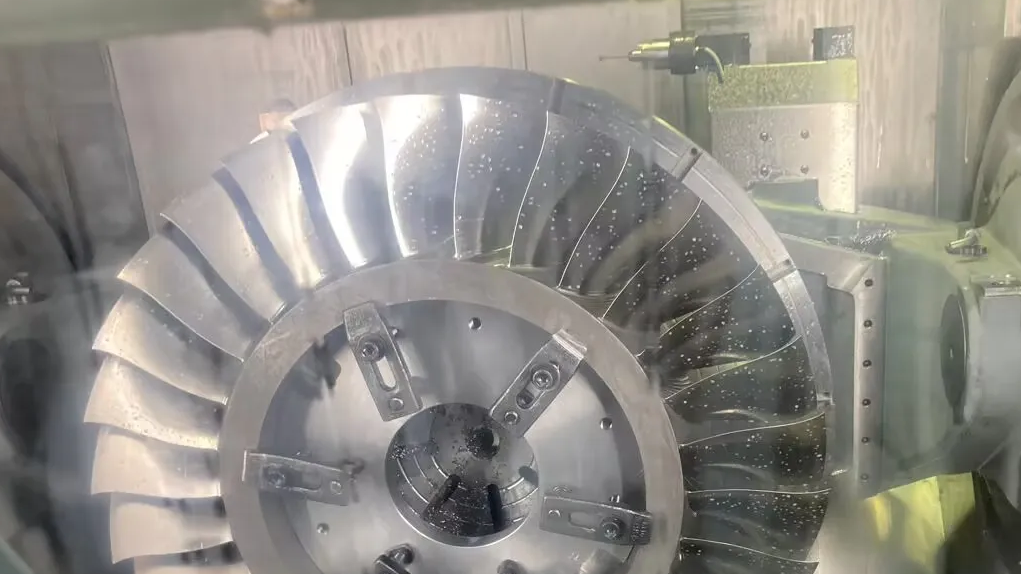
A blisk combines the disk and blades in one component. It replaces the dovetail slots and locking parts used to attach separate blades to a conventional disk. This changes the rotor structure and also changes how the part must be machined and inspected.
The rim does not need dovetail slots or separate blade locking hardware. The weight change is confirmed from the approved rotor design.
The blades and disk are made as one component. This removes individual blade attachment work and reduces the number of parts in the rotor assembly.
The blade roots and hub passage are machined from one model. This avoids the attachment gaps found in a rotor assembled from separate blades.
The rotor axis establishes the inspection datum. Blade position and hub geometry are then measured from that reference as the drawing requires.
The drawing identifies the material family, grade and supplied condition. We use that information to review the blank, tool access and finishing allowance before machining begins.
7075-T6
Used for development rotors, test hardware and low temperature industrial impellers when the drawing specifies aluminum.
We confirm the temper and blank form before machining. Thin blades still need a controlled cutting order during finishing.
Ti-6Al-4V Grade 5
Used for fan rotors, low pressure compressor rotors and selected compressor stages.
Cutting heat remains close to the tool edge. We limit engagement and check blade movement during finishing.
Ti-6Al-2Sn-4Zr-2Mo
Used for compressor rotors when the customer drawing specifies Ti-6242.
The supplied material condition and heat treatment are confirmed before cutting data and finishing allowance are set.
Inconel 718
Used for compressor rotors that work at higher temperatures under the approved engine specification.
Short tool engagement and controlled heat removal help protect the airfoil surface during machining.
Udimet 720
Used for high load rotor designs when this grade is stated in the material specification.
We confirm the material condition and stock route before quoting. Tool access is checked from the supplied model.
ATI 718Plus
Used for rotor programs that specify ATI 718Plus for elevated temperature service.
The machining plan is qualified for the supplied condition. Cutting data are established separately from Inconel 718 work.
The six stages below follow the order used to turn an approved model into an inspected rotor. Each stage produces information needed by the next one.
We confirm that the solid model matches the current drawing revision. The material specification establishes the blank condition, while the drawing datum sets the reference for programming and inspection.
The programmer selects a cutter that can reach the full passage. The tool axis is then checked through the material removal simulation and the complete machine simulation before code is released.
Material between the blades is removed in planned levels. The selected strategy keeps the cutter load within the stable range for the material and tool reach.
A controlled layer remains on each airfoil and the hub. The cutting order is arranged so one side of a thin blade is not fully released too early.
Point milling or flank milling is chosen from the surface form. The finishing pass covers both airfoil sides. The edges and tip are completed from the same approved model.
The rotor datum is established again for final measurement. Airfoil geometry is checked first. Runout and the specified surface condition are then recorded before release.
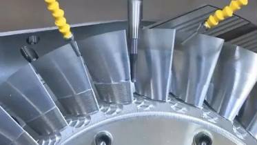
Blade spacing limits the available cutter diameter. Tool reach can introduce a separate stability problem, especially in a deep passage. We choose the roughing and finishing methods after both conditions have been checked in CAM.
Machining use
Initial passage roughing with high material removal.
Process control
Full radial engagement creates a high radial cutting force. Deep levels may be divided into more than one path.
Machining use
Roughing where reduced radial engagement improves cutting stability.
Process control
The path needs verified five axis motion and a machine with suitable dynamic response.
Machining use
Deep passages or long tool reach where side cutting becomes unstable.
Process control
The main cutting load is directed along the tool axis. Entry movement is checked first. Simulation then confirms clearance and a practical route for chip removal.
Machining use
Semifinishing or finishing of surfaces that suit line contact with the cutter.
Process control
Tool contact is checked over the full blade. A large contact area needs a stable machine and a controlled finishing pass.
Machining use
Twisted freeform surfaces and areas where flank contact cannot follow the geometry.
Process control
Ball nose or barrel cutters provide flexible access. More passes may be needed to reach the specified surface condition.
A thin blade can move while it is being cut even when the tool path is geometrically correct. We review the programmed stock, the machine motion and the expected cutting load before the finishing pass is released.
The in-process workpiece is compared with the final model after each programmed stage. This shows remaining stock and possible overcut before machining starts.
The posted program is checked on a digital model of the selected machine. The fixture and complete tool assembly are included so rotary travel and collision clearance can be reviewed.
The first finishing pass usually removes the most stock from the blade. Engagement is adjusted when the predicted load may bend the airfoil or mark its surface.
Stock is removed in a balanced order and local support is retained where the geometry allows. The blade is checked after the clamp load is released.
Finishing work follows the airfoil geometry that has already been accepted. The drawing or process specification must state where a treatment is required and which surfaces must remain protected.
Polishing removes the machining texture without changing the approved airfoil beyond its profile tolerance. Leading edges and trailing edges receive separate control.
Abrasive flow machining can reach selected flow passages where a conventional polishing tool has limited access. The allowed stock removal is set before treatment.
When shot peening is specified, the required intensity and coverage come from the process document. Thin edges and areas that must remain untreated are identified first.
Laser shock peening may be specified for selected high stress regions. The approved process controls the treated area while the finished airfoil geometry remains protected.
Measurement starts from the rotor datum in the approved drawing. The method must reach the required surface and provide enough accuracy for the stated tolerance.
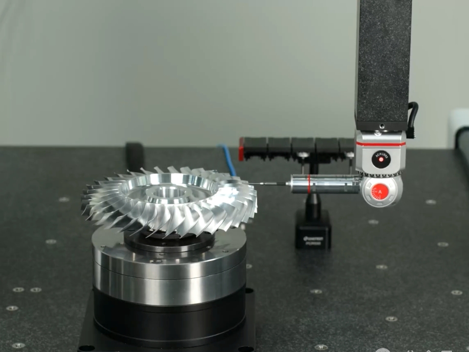
| Method | Measured work | Selection basis |
|---|---|---|
| Tactile CMM probing | The datum is established first. Required blade sections and accessible hub surfaces are then measured. | Used where the probe can reach the feature and the drawing requires point measurement. |
| Optical three dimensional scanning | Airfoil coverage and comparison with the nominal CAD surface. | Provides dense surface data. Visibility in narrow passages is reviewed before it is selected. |
| Surface roughness measurement | The specified blade, flow passage or disk surface is measured at the drawing location. | The stylus or optical method is selected for the surface and the specified roughness value. |
| Runout measurement | Runout is reported for the disk faces and other concentric features that reference the rotor axis. | The part is located from the drawing datum so the reported result matches the assembly requirement. |
Pressure side and suction side sections are compared with the nominal model at the locations required by the inspection plan.
Angular location and the relationship between blades are checked from the rotor datum.
The leading edge and trailing edge are checked for thickness, contour and local blending where the drawing provides an acceptance value.
The hub profile is checked for remaining stock or overcut. Inspection also covers the passage surface where it joins the blade root.
Blade tip position is measured from the specified axis. Disk face geometry and rotor runout are checked from the same datum setup.
Material certificates, first article reports, dimensional reports and treatment documents are supplied when they are included in the order.
Integrated rotors are used where the engine design calls for lower rotor mass and a continuous flow passage. The customer model and material specification define the work for each stage.
Large titanium fan blisks use long, thin blades. The process plan must protect the airfoil while keeping the rotor datum stable.
Integrated rotors reduce the number of blade attachment parts in compact compressor stages. Passage access is reviewed from the supplied model.
These stages can use titanium or nickel alloys under the engine material specification. Small passages make holder clearance and inspection access important.
Integrally bladed rotor designs are also used in industrial turbomachinery. The material and acceptance plan follow the customer drawing and service requirement.
Tell us what part you need and attach the current drawing.
We will review it before preparing a quote.