
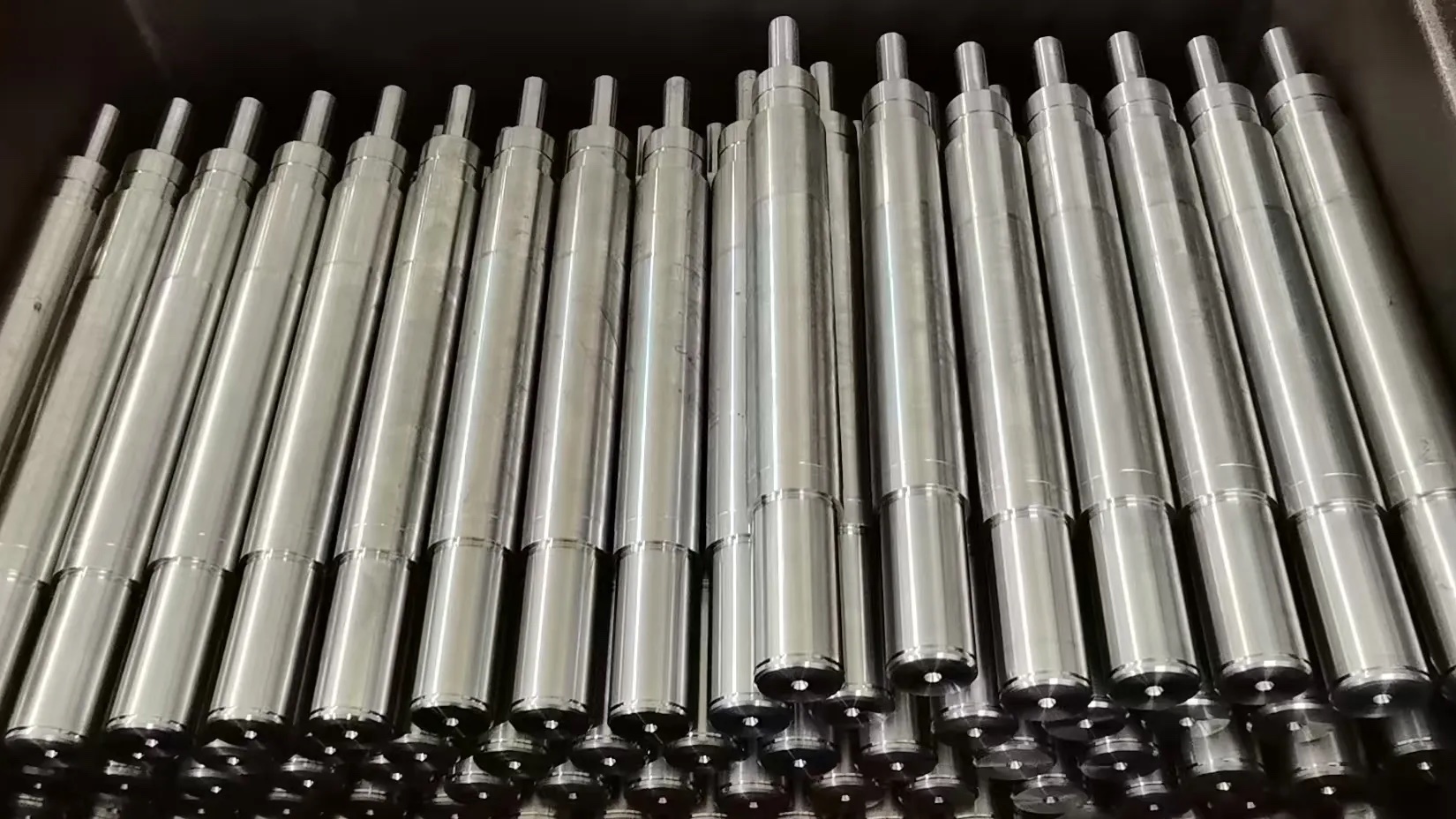
An accurate shaft requires more than turning a bar to diameter. The machining plan must keep the bearing journals aligned, leave enough stock to correct heat-treatment distortion, and protect the finished seats during keyway machining and handling. This guide explains how those decisions fit into a typical shaft manufacturing process.
What Shaft Manufacturing Involves
Shaft manufacturing produces the rotating components that support gears, pulleys, cams, and other transmission parts. A shaft transfers torque and carries the loads applied by those parts. Its bearing seats, shoulders, and mounting surfaces must work together so that the assembly rotates as intended.
Common designs include straight shafts, stepped shafts, tapered mandrels, hollow shafts, crankshafts, camshafts, eccentric shafts, and lead screws. Most combine cylindrical surfaces with shoulders, grooves, threads, or bores. CNC turning establishes the main rotational surfaces; milling, heat treatment, and grinding are added where the drawing requires them.
Length relative to diameter affects the setup. A length-to-diameter ratio below 5 is often described as a short shaft, while a ratio above 20 is commonly treated as slender. These are workshop guidelines rather than universal limits. The unsupported length and the smallest working diameter can matter more than the overall dimensions.
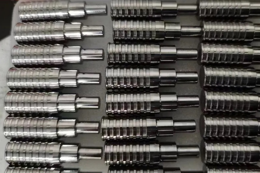
Shaft Journal Requirements for Manufacturing
The portion of a shaft that runs in a bearing is called a journal. Bearing journals locate the shaft in the assembly, so their diameter, form, and surface finish need particular attention. Seats for gears and pulleys also require a defined fit, but may have different tolerance requirements.
Typical process-planning references give IT5–IT7 as illustrative dimensional tolerance grades for support journals and IT6–IT9 for transmission-component seats. An IT grade describes the tolerance width for a nominal size; it does not define the complete fit. The drawing must also specify the tolerance-zone position and the mating component requirements.
Roundness and cylindricity control the shape of a journal. Runout requirements relate rotating surfaces to the specified datum axis. Do not assume that a diameter tolerance alone controls these errors. The drawing should identify the bearing datum surfaces and state the geometric limits needed by the assembly.
Illustrative surface-finish ranges include Ra 0.63–2.5 μm for some transmission seats and Ra 0.16–0.63 μm for some precision bearing journals. These are examples, not default requirements. Bearing type, seat size, fit, and operating conditions determine the appropriate finish. An unnecessarily fine finish adds work without necessarily improving bearing performance.
Selecting Material for Shaft Manufacturing
Round bar is a practical starting point when the finished diameters are close to one another. It is particularly useful for small batches because it avoids a dedicated forging tool. The selected bar diameter must leave enough material to remove the original surface and machine every finished feature.
A forging can be more suitable when a stepped shaft has large changes in diameter or needs mechanical properties associated with a specified forging route. Bringing the blank closer to the final shape reduces the amount of metal removed. Open-die forging is often considered for smaller quantities; closed-die forging can be suitable when production volume justifies the tooling.
Stock selection also includes checking the material condition, straightness, and available machining allowance. A blank that is only slightly larger than the maximum finished diameter may still be unsuitable if scale, bending, or heat-treatment distortion cannot be cleaned up.
Grade 45 medium-carbon steel is a common option for general transmission shafts. Normalizing or quenching and tempering can provide a useful combination of machinability, strength, and toughness. The required condition should be stated on the drawing or purchase specification.
40Cr alloy structural steel is used where the specified strength and heat-treatment response call for an alloy steel. Its suitability for a higher-speed shaft still requires a review of the loads, section size, and finished geometry. A material name alone does not establish an acceptable operating speed.
GCr15 bearing steel and 65Mn spring steel may be considered for particular wear-resistant shaft applications, but they require different heat-treatment procedures. A range of 50–58 HRC may be specified for selected hardened surfaces. That range should not be treated as a guaranteed result for either grade or for every section size.
38CrMoAlA nitriding steel can provide a hard surface over a tougher core after suitable core treatment and nitriding. Nitriding can reduce distortion compared with treatments that require a subsequent quench, but it does not eliminate dimensional change. Case depth, hardness, and any finishing allowance must be agreed before machining.
** Material grades and numerical values in this article are process references. Confirm the applicable material standard, certified condition, and heat-treatment specification for the actual part. Grades from different national standards should not be substituted solely because their names appear comparable.
Planning the Shaft Manufacturing Process
A transmission shaft requiring IT7 dimensional accuracy and a ground finish around Ra 0.4–0.8 μm may follow the sequence below. This example describes a shaft with hardened journals; other material conditions require a revised route.
1. Prepare the blank and normalize it if that treatment is specified. Face the ends and drill the center holes.
2. Rough-turn the outside diameters and shoulders, leaving stock for subsequent operations. If quenching and tempering is required for the core properties, it is commonly scheduled after rough machining and before final sizing.
3. Semi-finish or finish-turn the rotational surfaces while retaining the allowance required for hardening and grinding.
4. Machine the keyways or splines, then deburr the edges. Complete the specified hardening operation before grinding the affected journals.
5. Inspect and, where necessary, restore the center holes. Check distortion before cylindrical grinding.
6. Rough-grind and finish-grind the specified surfaces, then inspect the finished shaft against the drawing.
The heat-treatment plan must distinguish core treatment from surface hardening. Moving all heat treatment to one point in the route can leave unsuitable material for cutting or insufficient stock to correct distortion.
Center holes allow a shaft to be supported between centers during successive turning and grinding operations. Reusing these locating features helps maintain a consistent machining axis. For small batches, the ends can be faced and center-drilled on a lathe; repeated production may use dedicated facing and centering equipment.
During roughing, a chuck can grip the outside surface while a tailstock center supports the opposite end. Later operations may use two centers to improve repeatability, provided the part geometry and drive arrangement allow it.
Center holes must remain clean and undamaged. Heat treatment, handling, or repeated loading can change their contact surfaces. Inspect them and restore them using a suitable center-hole finishing method when needed before precision grinding. Simply reusing damaged centers can reproduce alignment errors throughout the remaining operations.
Keyways are often milled after the adjacent outside diameters have been finish-turned and before final cylindrical grinding. Cutting a keyway too early creates an interrupted surface during later turning, which can increase vibration and complicate edge control.
Cutting it after final grinding risks damaging the finished seat through clamping, burr formation, or handling. The selected order should leave access for deburring without changing the finished diameter.
Spline manufacturing needs its own process review. Milling, hobbing, or grinding may be selected to meet the tooth geometry and accuracy requirements. A spline that requires hard finishing will not necessarily follow the same sequence as a simple milled keyway.
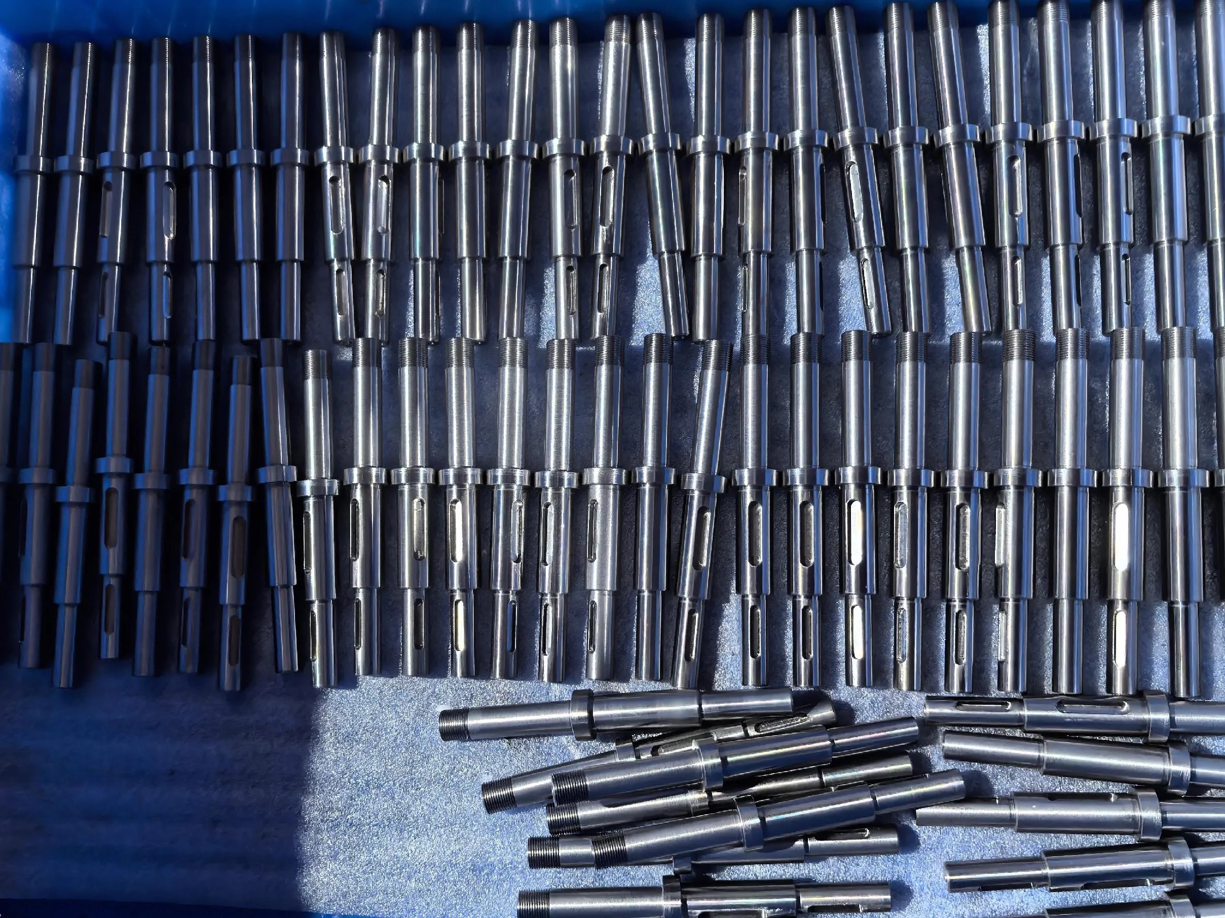
Workholding for Shaft Machining
A hollow shaft may not have solid ends that accept conventional center holes. A suitable tapered plug or mandrel with a center hole can provide support, provided it locates securely without distorting the bore.
When the outside surfaces and internal taper are machined in separate setups, the relationship between them must be checked each time the locating tool is installed. Indicate the relevant finished surface and correct the setup before continuing. Where required, restore the center reference rather than assuming that a reinstalled plug reproduces the previous axis.
Thin walls also require controlled clamping pressure. Check whether the measured diameter changes after releasing the part, since a surface that appears round while clamped may spring out of shape when unloaded.
A slender shaft bends easily under radial cutting force. Chatter, taper, and inconsistent diameter can result even when the machine follows the programmed path correctly. The setup should support the cutting zone and allow for thermal expansion.
A chuck and tailstock arrangement can support rough turning. Where appropriate, a spring-loaded or otherwise compliant center accommodates axial growth as the workpiece heats. Excessive tailstock force can bow the shaft instead of improving support.
A follower rest moves with the tool to resist radial deflection, while a steady rest supports a selected position along the shaft. Their contact surfaces must be aligned with the spindle axis and kept in suitable condition to avoid marking the workpiece.
In suitable setups, feeding the tool toward the tailstock can help reduce the tendency for the shaft to bend under axial compression. This is not a universal instruction to reverse the feed: the tool geometry, workholding, and force direction must be reviewed together.
Sharp tools and a suitable entering angle can reduce radial force. Chip control is equally necessary so that chips do not wrap around the shaft, damage the finished surface, or interfere with the support. Check the diameter at several positions as machining progresses.
A Small Batch Stepped Shaft Example
Consider a process-planning example of a stepped transmission shaft with nominal journals of 80 mm, 65 mm, and 55 mm, plus keyways on the 80 mm and 55 mm sections. The example uses 95 mm diameter hot-rolled Grade 45 bar and calls for quenching and tempering.
For this relatively modest difference in finished diameters, bar stock is a reasonable candidate for small-batch production. Its suitability still needs confirmation against the complete shaft length, stock condition, and required machining allowance. A forging should be reviewed if the actual design has larger steps or a specified mechanical-property requirement that favors it.
Rough machining can use a chuck with tailstock support. After the specified core heat treatment, the journals can be brought closer to size using consistent center references. Keyway machining, any additional specified hardening, center restoration, and grinding are then scheduled around the final fit and finish requirements.
This example illustrates process planning rather than defining a complete production drawing. Shoulder positions, keyway sizes, fits, geometric tolerances, and surface requirements remain necessary before releasing a machining plan.
Inspecting Finished Shafts Before Delivery
Measure each journal at multiple axial positions and angular orientations to check size variation. Verify the specified form and runout using equipment capable of resolving the drawing limits. A single micrometer reading cannot establish cylindricity or the relationship between two journals.
Check shoulder locations, keyway dimensions, threads, and bores using the specified datums. Measure surface roughness on the required seats, and verify hardness or case requirements when heat treatment forms part of the specification. Inspect for burrs and handling damage before protecting finished surfaces for delivery.
For a shaft machining review, provide the complete drawing and identify the mating bearings or components where possible. State the material condition and heat-treatment requirements. This allows the machining team to establish the locating method, finishing allowance, and inspection sequence before production begins.